

 EN
EN

 English
 русский
 Français
 Español
 عربى
عربى
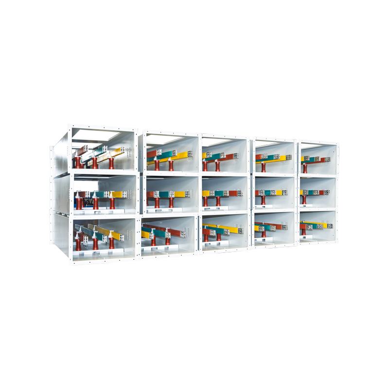


Busbar Temperature Rise Calculation: Formula, Example, IEC and UL Limits
Content
- 1 Start with the Steady-State Heat Balance
- 2 The Practical Sizing Formula
- 3 Worked Example: 2000 A Copper Busbar
- 4 Copper vs Aluminium: What Changes in the Calculation
- 5 Skin Effect and the Shape of the Bar
- 6 Ambient Temperature, Enclosures, and Derating
- 7 Standards and Allowable Temperature-Rise Limits
- 8 Common Calculation Mistakes to Avoid
- 9 Frequently Asked Questions
During a routine temperature-rise test, a 2000 A switchboard failed because its main busbar reached 112 K above ambient - 7 K over the limit. The conductor size had been copied from an earlier design that ran cooler. The difference was not the load; it was the heat balance set by enclosure ventilation, material choice, and conductor shape.
Temperature rise controls the continuous rating of a busbar, the life of its insulation, and the safety of bolted joints. This article explains the busbar temperature rise calculation from the heat balance, shows a 2000 A design example, and summarizes the limits in IEC 61439-1 and UL 891.
Start with the Steady-State Heat Balance
At steady state, a busbar reaches a stable temperature when the heat generated by its own resistance equals the heat rejected to the surroundings. In short: a busbar has no single fixed rating; it has a temperature rise curve that changes with the cooling environment.
The generated heat is Joule heating: Q_gen = I² × R_ac.
The rejected heat leaves by convection and radiation: Q_diss = h × S × ΔT + ε × σ × S × (Ts4 - Ta4).
For design work, both loss paths are combined into an equivalent coefficient h, giving:
ΔT = (I² × R_ac) / (h × S)
where:
- I - RMS current (A)
- R_ac - AC resistance at operating temperature (Ω)
- h - combined convection and radiation coefficient (W/m²·K)
- S - effective cooling surface area (m²)
- ΔT - temperature rise above ambient (K)
The relationship is quadratic: if current doubles, losses quadruple. A bar that stays cool at 800 A can overheat at 1250 A in the same cubicle.
Temperature rise vs current for a 160 × 10 mm copper bar
The Practical Sizing Formula
For quick estimation, engineers rearrange the heat balance into ampacity form:
I = K × √(A × ΔT)
where A is the cross-section in mm², ΔT is the allowable rise in K, and K is an empirical constant that bundles resistivity, surface finish, and ventilation. The minimum section is:
A = I² / (K² × ΔT)
| Arrangement | Copper (K) | Aluminium (K) |
|---|---|---|
| Single bar in free air | 11-13 | 8.5-10 |
| Bar in a ventilated enclosure | 9-11 | 7-8.5 |
| Bar in a sealed or unventilated enclosure | 7-9 | 5.5-7 |
Treat these constants as a starting point. A final design must be verified by calculation or type test, especially in compact assemblies.
Worked Example: 2000 A Copper Busbar
Size a 2000 A LV distribution board busbar with an allowable rise of 40 K inside a ventilated enclosure.
Step 1 - Select the material constant
For copper in a ventilated enclosure, take K = 8.5 (mid-range).
Step 2 - Calculate the minimum cross-section
A = 2000² / (8.5² × 40) = 4,000,000 / 2890 = 1384 mm²
Step 3 - Choose a standard bar
A 160 × 10 mm bar gives 1600 mm², about 16% above the minimum. A 125 × 12 mm bar (1500 mm²) also fits many panel layouts.
Step 4 - Verify the resulting temperature rise
ΔT = (2000 / 8.5)² / 1600 = 34.6 K, below the 40 K limit. At 2400 A the same bar rises to 49.8 K - over the limit. The last 20% of current adds about 44% more temperature rise.
Copper vs Aluminium: What Changes in the Calculation
Material choice changes K and therefore the physical section. Aluminium has about 64% higher resistivity than copper, so it needs roughly 1.6 to 1.7 times the cross-section for the same current and rise. In return it weighs about 70% less, which reduces support loads and can offset the larger section price in long runs.
| Property | Copper | Aluminium |
|---|---|---|
| Resistivity at 20 °C (Ω·mm²/m) | 0.0172 | 0.0282 |
| Temperature coefficient (1/K) | 0.00393 | 0.00403 |
| Relative ampacity at same cross-section | 1.00 | ~0.78 |
| Cross-section needed for same ampacity | baseline | ~1.6x |
| Weight for the same ampacity | baseline | ~50% less |
For the 2000 A, 40 K example, aluminium needs about 2367 mm², typically two 100 × 12 mm bars per phase. Aluminium joints also need careful surface preparation because the surface oxide film adds contact resistance and creates hot spots.
Required cross-section for 2000 A at 40 K rise
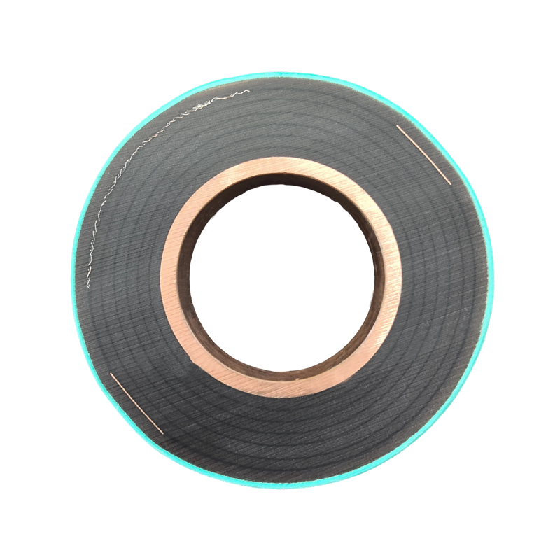
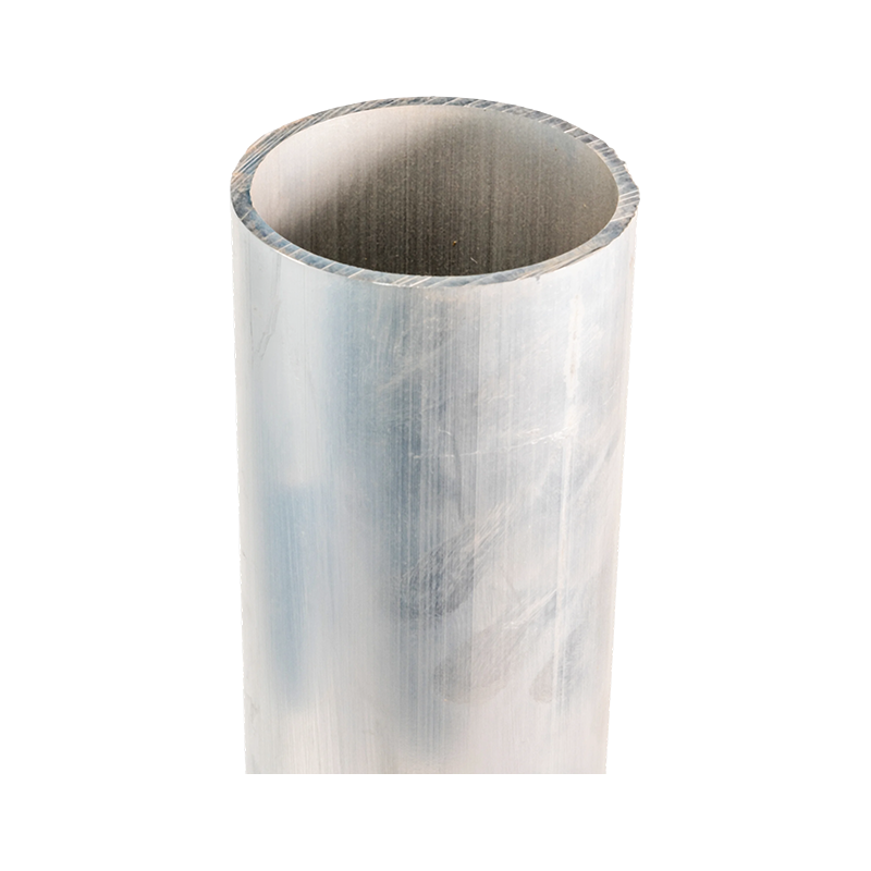 Magnesium-Aluminum Alloy Tubular Busbar for High-Voltage StationsThis tubular busbar line covers multiple alloys and voltage classes up to 1000 kV, making it a practical choice when sizing conductors for high-current outdoor substations where thermal limits and mechanical strength both matter.View Product →
Aluminium is also common as tube conductor in outdoor substations. The thermal logic is the same, but a tube has less cooling surface per unit cross-section than a flat bar, so selecting the right aluminium alloy tubular busbar starts with the allowable temperature rise and then considers mechanical strength.
Skin Effect and the Shape of the Bar
At 50/60 Hz, AC resistance exceeds DC resistance because current crowds toward the surface. A wide thin bar such as 160 × 10 mm has a better AC-to-DC ratio than a 50 × 32 mm bar of the same section, since more material stays near the cooling surface.
Keep the width-to-thickness ratio above 10:1 where possible. For multiple bars per phase, space them by at least one bar thickness so each surface can dissipate heat.
Ambient Temperature, Enclosures, and Derating
Temperature rise is a difference, while insulation and equipment ratings are absolute temperatures. A 40 K rise is safe at 35 °C ambient but unacceptable at 45 °C ambient. Always convert the allowed rise to an absolute conductor temperature: T = T_ambient + ΔT.
| Condition | Derating factor |
|---|---|
| Ventilated enclosure | 0.85-0.92 |
| Sealed (unventilated) enclosure | 0.70-0.80 |
| Ambient 40 °C instead of 35 °C | 0.93-0.98 |
| Altitude 2000 m | ~0.95 |
Enclosure design causes more failures than the conductor calculation itself. A sealed IP54 cubicle can cut the rating by 20-30% compared with free air because convection nearly disappears.
- Convection - 70%
- Radiation - 22%
- Supports - 8%
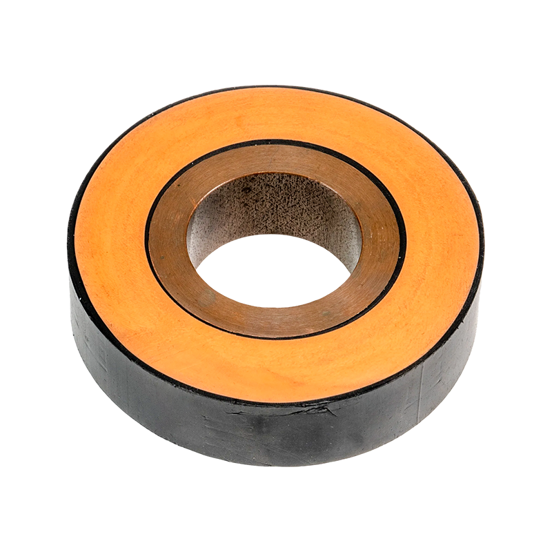
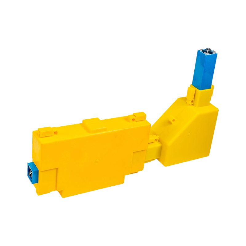 Fully Enclosed Power Busway with High Current RatingGiven that enclosure design can reduce ampacity by 20–30%, this factory-built busway offers a tested temperature rise and ratings up to 6300 A, removing guesswork for installations in IP54 or sealed environments.View Product →
A factory-built busway with a known enclosure and tested temperature rise removes much of this guesswork; its catalogue rating already reflects a defined thermal test.
Standards and Allowable Temperature-Rise Limits
Most switchgear specifications cite IEC 61439-1 or UL 891. Both verify temperature rise on the assembled product, not on the bare conductor. The values below are the commonly used limits; the contract edition of the standard takes precedence.
| Standard | Component | Typical limit |
|---|---|---|
| IEC 61439-1 | Terminals for external conductors | 70 K |
| IEC 61439-1 | Bare copper internal connections | 105 K |
| IEC 61439-1 | Bare aluminium internal connections | 90 K |
| UL 891 | Main busbars in a switchboard | 65 K |
When the conductor is insulated, the rise limit drops because the insulation material has a maximum continuous operating temperature. The check then targets the hot spot at the conductor-insulation interface, and the insulation thickness becomes part of the thermal resistance.
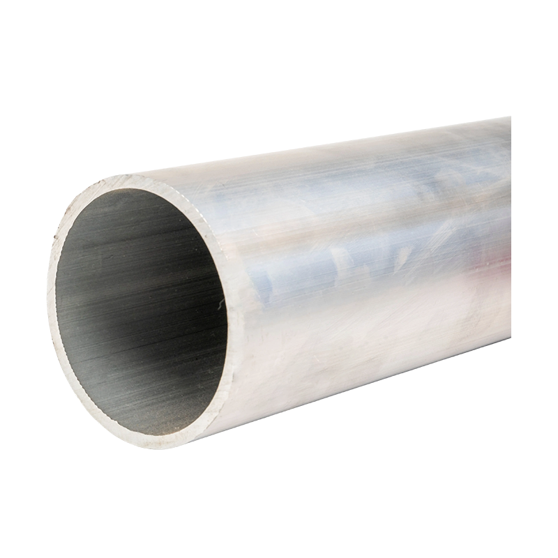
 Epoxy Resin Cast Tubular Busbar with Integrated InsulationThis product's one-shot molded insulation and shielding address the hotspot at the conductor-insulation interface; its long-life, flame-retardant structure suits applications where continuous conductor temperature and surface temperature both need verification.View Product →
Fully insulated tubular busbars therefore need two checks: conductor temperature and outer surface temperature. For short-circuit conditions, this continuous calculation does not apply - use the adiabatic equation for fault withstand instead.
Common Calculation Mistakes to Avoid
- Using DC resistance instead of AC resistance - skin and proximity effects add 10-30% loss in large bars.
- Applying free-air ratings to an enclosed busbar - a sealed enclosure reduces the rating by 20-30%.
- Ignoring the ambient basis - a 90 K rise is fine at 35 °C but exceeds many insulation limits at 50 °C.
- Forgetting harmonics - triplen harmonics raise RMS current and heating beyond the fundamental value.
- Sizing to nominal load instead of contingency load - always check the highest credible operating current.
- Neglecting joints and terminations - a poor bolted joint fails before the main conductor does.
Frequently Asked Questions
How do you calculate the temperature rise of a busbar?
Use ΔT = (I/K)²/A or the heat balance ΔT = I²R/(hS), then compare the result with the applicable standard limit for the component.
What is the allowable temperature rise for a busbar?
IEC 61439-1 commonly allows 105 K for bare copper internal connections; UL 891 is stricter for switchboard busbars at 65 K. Insulated conductors follow the insulation temperature class instead.
Does aluminium run hotter than copper at the same current?
With the same cross-section and current, yes. Aluminium needs about 1.6 times the copper cross-section to reach the same steady-state temperature rise.
What ambient temperature should be used in the calculation?
Use the maximum specified ambient, usually 35 °C or 40 °C. The conductor temperature equals ambient plus the calculated rise, and both must stay within the material or insulation limit.
Busbar temperature rise calculation is not academic. It decides whether a switchboard passes its type test, whether a busway carries its nameplate current on a hot afternoon, and whether insulation ages prematurely. Calculate at the highest credible current, apply a realistic enclosure derating, and pick a conductor whose material and cross-section match the thermal environment.
When the application involves high currents or limited space, a manufacturer with type-tested busbar and busway products can supply both the hardware and the supporting thermal documentation.



-
 +86-180 3625 3000
-
 admin@wpbusbar.com
-
 No. 8, Yanjin Road, Chengxi Industrial Park, Shanyang Town, Baoying County, Yangzhou City, Jiangsu Province, China
Copyright © Jiangsu Wopeng Power Technology Co., Ltd.
All Rights Reserved.
 Custom Insulated Bus Bar Manufacturer
Tubular Busbar System Factory
Custom Insulated Bus Bar Manufacturer
Tubular Busbar System Factory