

 EN
EN

 English
 русский
 Français
 Español
 عربى
عربى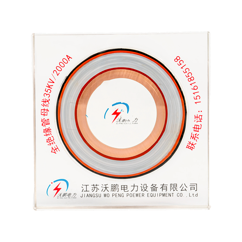
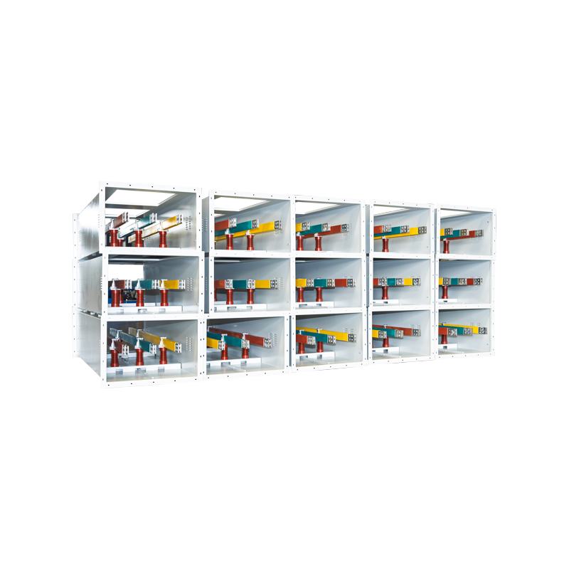


Busbar Fabrication Guide: Process Steps, Materials, and Quality Control
Content
- 1 What Busbar Fabrication Actually Covers
- 2 The Core Fabrication Steps, in Order
- 3 Copper or Aluminum? The Fabrication Consequences
- 4 Insulation: Where Tubular Busbars Earn Their Protection
- 5 Quality Control That Predicts Field Performance
- 6 Common Defects and How Shops Catch Them Early
- 7 What Buyers Should Verify Before Ordering
- 8 Frequently Asked Questions
At 3 p.m. on the hottest afternoon of the year, a 4,000 A switchboard in a coastal plant trips for the third time that week. The design was sound and the breaker tested fine. The real culprit: a bolted joint on a main bar that was punched, left with a raised burr, and torqued down anyway. The burr buried most of the contact area, resistance crept upward, and every daily heat cycle pushed the joint closer to failure.
This story repeats across the industry because busbar fabrication — cutting, punching, bending, plating, insulating, and testing — is where a sound electrical design either survives or quietly falls apart. The conclusion comes first: material selection and joint quality determine a busbar system's service life far more than anything printed on its nameplate. The walkthrough below covers the core fabrication steps, the copper-versus-aluminum decision, how tubular busbars are insulated, the tests that actually predict field performance, and what buyers should verify before signing a purchase order.
What Busbar Fabrication Actually Covers
Fabrication converts raw conductor stock — typically electrolytic copper bar or extruded aluminum alloy tube — into finished, ready-to-install current carriers. It spans three quite different workflows:
- Flat-bar fabrication: cutting, punching, bending, and plating rectangular bar for switchboards, panel boards, and distribution assemblies.
- Tubular busbar fabrication: cutting rigid aluminum or copper tube to length, welding end fittings and splices, and fitting post insulators and fixing brackets — the standard for high-voltage substations, where tube spans between steel structures.
- Busway assembly: housing insulated conductors inside a compact enclosure for medium- and low-voltage distribution, including high-density systems for commercial and industrial buildings.
The steps overlap, but tolerances, tooling, and failure modes do not. A shop that turns out excellent panel bars is not automatically qualified to weld substation tube or cast insulation under vacuum, which is why each capability deserves separate scrutiny when you evaluate suppliers.
The Core Fabrication Steps, in Order
Regardless of product type, disciplined shops follow the same six-stage sequence:
- Material selection and preparation — verify alloy grade and temper against mill certificates, then straighten and clean stock before cutting begins.
- Cutting and sizing — shear, saw, or CNC-cut to length with square faces; those faces later become part of the joint surface.
- Punching and drilling — CNC punching typically holds hole positions within ±0.1–0.2 mm, and hole placement directly determines how much contact area each bolted joint gets.
- Bending and forming — the inside bend radius should be at least equal to bar thickness for copper; aluminum demands more generous radii and attention to grain direction, or the outer face cracks.
- Surface treatment — degrease and deoxidize, tin or silver plate joint areas, or apply full insulation on higher-voltage products.
- Inspection and testing — dimensional checks, hole gauges, plating adhesion sampling, and electrical testing on insulated products before shipment.
Surface choice deserves its own decision, because it trades cost against joint stability:
| Treatment | What It Delivers | Typical Use | Watch-Outs |
|---|---|---|---|
| Bare (cleaned, deoxidized) | Lowest cost; relies on high clamping pressure | Dry indoor switchgear | Oxidation raises joint resistance over time |
| Tin plating | Slows oxidation; forgiving for bolted joints | General power distribution, humid indoor sites | Softer surface; control torque and avoid over-compression |
| Silver plating | Lowest contact resistance; tolerates higher temperatures | High-current joints, frequent load cycling | Higher cost; scratches expose base metal |
| Epoxy resin casting | Full dielectric layer; enables compact layouts | 35 kV-class tubular busbars | Void control and cure quality are critical |
Bending generates the most rework in typical production. A bar bent too tightly, or across the rolling grain, can look flawless and still carry micro-cracks that grow under decades of thermal cycling. Put radius and grain requirements on the drawing, not in the operator's memory.
Copper or Aluminum? The Fabrication Consequences
On volume conductivity, copper wins: about 100% IACS against roughly 61% for aluminum. But copper is also about 3.3 times denser, and that changes the arithmetic completely. To carry the same current, an aluminum bar needs roughly 1.6 times the cross-section — yet still weighs close to half as much and costs less per ampere carried.
Weight explains why rigid tubular busbars in substations are almost always aluminum alloy: every extra kilogram on a long span multiplies into bigger supports, foundations, and installation cost. Magnesium-aluminum compositions add the strength that long outdoor spans and short-circuit forces demand.
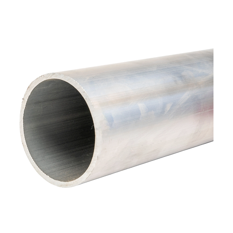
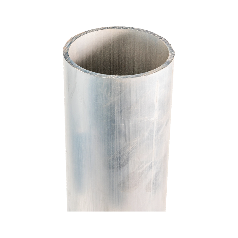 Ultra-High Voltage Magnesium-Aluminum Alloy Tubular Bus BarAvailable in 6063G, LF21Y, 6R05, and 2A14 alloys for 220 kV to 1000 kV systems, this seamless tubular conductor combines the light weight and alloy strength that long outdoor substation spans and short-circuit forces demand.View Product →
Fabrication follows the material. Aluminum re-oxidizes within minutes of cleaning, so joint faces must be deoxidized and assembled promptly. Springback after bending is higher, bend radii larger, and welding requires procedures qualified for the specific alloy — generic copper-shop habits transfer poorly.
Insulation: Where Tubular Busbars Earn Their Protection
On medium- and high-voltage tubular busbars, the bare conductor is only half the product. The insulation system sets creepage distances, phase clearances, partial discharge behavior, and how compact the installation can be. The main routes are heat-shrink sleeves at the basic end; extruded EPDM or silicone rubber; PTFE for high-temperature and chemically aggressive environments; and epoxy resin casting for higher voltage classes.
Casting is where fabrication discipline shows most clearly. Under vacuum casting, air and volatiles are extracted before the resin cures, leaving no voids to seed partial discharge. An insulated bar without that control can pass a factory withstand test and still age prematurely in service — one reason 35 kV-class products are routinely screened with partial discharge measurement.
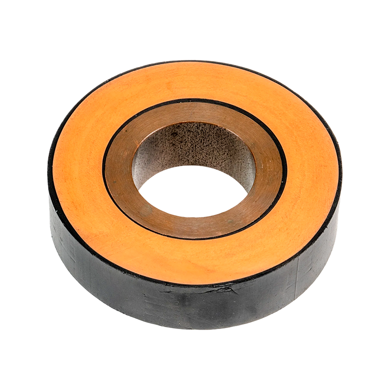
 Epoxy Resin Casting Tubular Bus BarVacuum-cast in a single seamless molding from oxygen-free copper, this flame-retardant 35 kV-class bar eliminates insulation interfaces and voids, supporting partial-discharge screening and a service life exceeding 30 years.View Product →
Quality Control That Predicts Field Performance
Three test families separate a rigorous fabricator from an optimistic one:
- Temperature-rise testing. Under IEC 61439-1, an assembly runs at rated current until temperatures stabilize, with bare copper busbars limited to a 105 K rise above ambient. Because heating in resistive joints scales roughly with the square of current, even modest extra joint resistance shows up quickly at rated load.
- Joint and plating checks. Hole-position gauges, torque verification, and plating adhesion sampling catch the defects that become hot spots later.
- Insulation tests. Power-frequency withstand plus partial discharge measurement, particularly for cast and extruded systems.
Common Defects and How Shops Catch Them Early
Most rework in busbar production traces back to a short list of recurring causes. The proportions below are illustrative rather than statistical, but experienced production managers will recognize the shape of the chart:
- Burrs and sharp edges after cutting or punching — fixed by making deburring a mandatory, signed-off step rather than an optional one.
- Cracks after bending — prevented by respecting minimum bend radii and bending against the rolling grain where the design allows.
- Hole misalignment — controlled with CNC punching and go/no-go gauges instead of manual layout.
- Plating delamination — caught by adhesion sampling on every batch, not only the first article.
- Insulation voids — eliminated through vacuum casting and routine partial discharge screening.
What Buyers Should Verify Before Ordering
When evaluating a fabricator, swap generic questions for concrete ones:
- Can they supply mill certificates tying every batch to a stated alloy grade and temper?
- Are cutting, punching, bending, welding, and insulation done in-house, or subcontracted to unknown third parties?
- For tubular products: which welding procedures and splice designs are qualified, and can they show test records?
- For insulated products: is casting performed under vacuum, and do they run routine partial discharge tests?
- Which tolerances will they commit to on hole positions, straightness, and finished length — in writing?
Insulation selection belongs in the same conversation. PTFE holds stable in high-temperature and chemically aggressive settings where rubber systems age faster, while vacuum-cast epoxy suits high-voltage classes and compact substations.
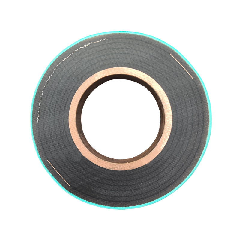
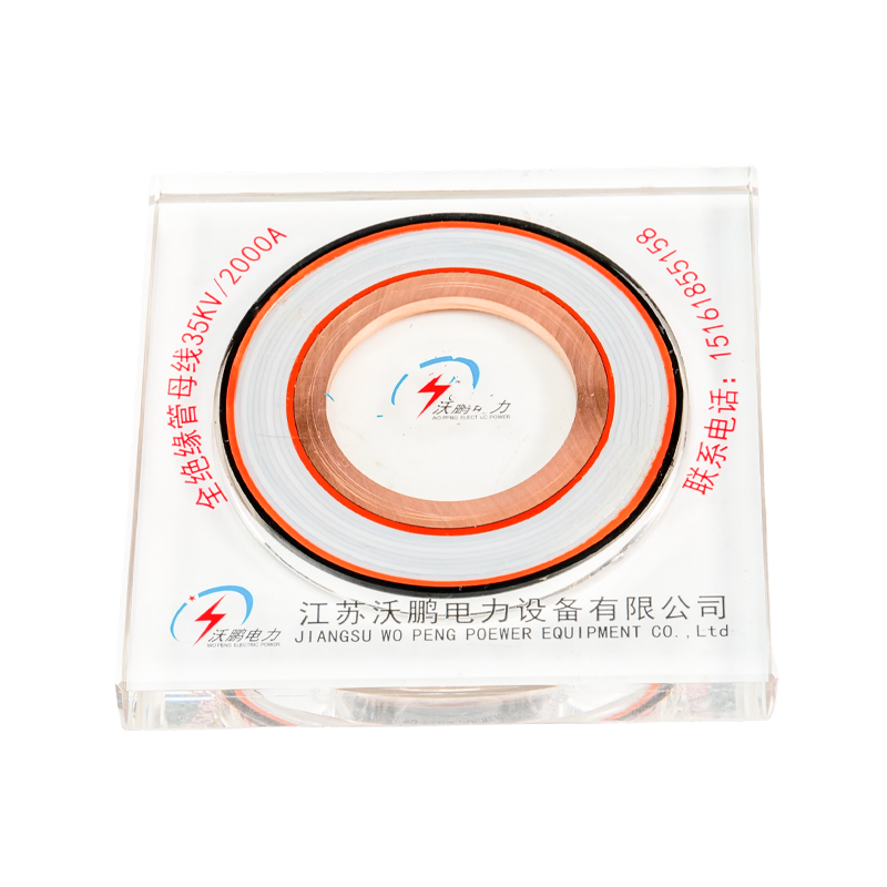 PTFE Tubular Bus BarWith PTFE film winding, multiple capacitive screens, and an operating range of -60°C to 250°C plus IP68 protection, this insulated bar suits high-temperature, chemically aggressive, and compact substation installations.View Product →
The selection logic repeats across conductor types. Before locking specifications, it is worth reading a dedicated walkthrough of how to select the right aluminum alloy tubular bus bar, then taking a shortlist of requirements to the fabricator rather than the other way around.
Frequently Asked Questions
What tolerance can a fabricator realistically hold on hole positions?
CNC punching typically holds ±0.1–0.2 mm on hole centers; manual drilling from scribed lines can drift toward ±0.5 mm or worse. For bolted joints, consistency across mating bars matters more than the absolute number, so ask how the shop fixtures mating parts together.
Can aluminum busbars replace copper everywhere?
No. Aluminum wins on weight and cost per ampere in open runs and long spans, but copper still makes sense where space is tight, joints are numerous, or the surrounding infrastructure is copper. Aluminum-to-copper connections need deliberate transition design and hardware.
How is tubular busbar fabrication different from flat bar work?
Tube adds extrusion or drawing, square cut-to-length, welding of joints and end fittings, and mechanical design for span loading and short-circuit forces. Post insulators and fixing brackets are part of the system, not accessories bolted on afterward.
What should a fabrication quotation include?
At minimum: alloy and temper, dimensional tolerances, insulation class and process, the test reports supplied with shipment, and packaging designed for long rigid sections. If a supplier hesitates to put those in writing, treat it as data. For a tubular busbar system matched to your voltage, span, and environment, you can request a specification review and compare responses side by side.
Recommended Products



-
 +86-180 3625 3000
-
 admin@wpbusbar.com
-
 No. 8, Yanjin Road, Chengxi Industrial Park, Shanyang Town, Baoying County, Yangzhou City, Jiangsu Province, China
Copyright © Jiangsu Wopeng Power Technology Co., Ltd.
All Rights Reserved.
 Custom Insulated Bus Bar Manufacturer
Tubular Busbar System Factory
Custom Insulated Bus Bar Manufacturer
Tubular Busbar System Factory