

 EN
EN

 English
 русский
 Français
 Español
 عربى
عربى


Busbar Short Circuit Withstand Rating Explained: Icw, Ipk, and IEC Standards
Content
- 1 What the Short Circuit Withstand Rating Actually Measures
- 2 Why the Rating Decides the Difference Between a Fault and a Disaster
- 3 How the Rating Is Verified: Standards, Type Tests, and Honest Data
- 4 What Determines How Much Short-Circuit Current a Busbar Can Survive
- 5 How to Specify the Right Short-Circuit Withstand Rating
- 6 Frequently Asked Questions About Short-Circuit Withstand Ratings
When a busbar arrives on site, the nameplate carries a group of values that look simple but are easy to misread: Icw = 50 kA / 1 s, Ipk = 105 kA. If you are the engineer responsible for the substation, or the system integrator buying the busway, this short circuit withstand rating tells you whether the conductor will survive a fault or fail in the first half cycle. In short, the rating defines the maximum short-circuit stress the busbar can withstand without permanent deformation, insulation breakdown, or damage to joints. Once you understand two values, Icw and Ipk, the whole rating becomes an engineering tool instead of a datasheet number.
What the Short Circuit Withstand Rating Actually Measures
A short circuit sends a current through the busbar that can be tens of times higher than the rated current. The busbar has to survive two different effects at the same time: heating from the current and mechanical force between the conductors. Every complete rating therefore contains two values.
Short-Time Withstand Current (Icw)
Icw is the RMS value of current the busbar can carry for a stated duration, normally 1 s, 3 s, or 4 s, without exceeding the maximum permitted temperature. The thermal effect follows I²t, which means the same temperature rise can result from a small current over a long time or a large current over a short time. For procurement, the duration is as important as the current itself.
Peak Withstand Current (Ipk)
Ipk is the highest instantaneous value of the current in the first half cycle of the fault. This peak produces the electrodynamic force between busbar phases, and the force is proportional to the square of the current. A 50 kA RMS fault at the first peak behaves like a hammer blow, not like a steady load. Standards define the relationship between Ipk and Icw with a factor n.
| Rated short-time withstand current Icw | Peak factor n (Ipk / Icw) |
|---|---|
| 10 kA < Icw ≤ 20 kA | 2.0 |
| 20 kA < Icw ≤ 50 kA | 2.1 |
| 50 kA < Icw ≤ 100 kA | 2.2 |
For a 50 kA / 1 s busbar, the peak withstand current is therefore typically 105 kA. If the installation has a high asymmetry factor, the actual first peak can be higher, which is why the peak value must be checked against the network calculation rather than assumed.
Why the Rating Decides the Difference Between a Fault and a Disaster
Selecting a busbar with too low a short circuit withstand rating is one of the most dangerous errors in electrical design, because the failure appears only under fault conditions, when it is too late to correct.
The thermal effect is immediate. During a short circuit, heat is generated faster than it can be dissipated, so the conductor heats almost adiabatically. In one second, a conductor starting at 65 °C can reach 200 °C or more, depending on current density. Bolted joints are the weakest link: at high temperature, bolt pressure relaxes, contact resistance rises, and the joint can fail even when the visible conductor looks intact.
The mechanical effect is even more dramatic. Two parallel busbar conductors 100 mm apart carrying a 100 kA peak current experience a force of roughly 20,000 N per meter, equivalent to hanging a two-tonne weight on every meter of the busbar. Bending, insulator cracking, and phase-to-phase arcs are typical results when the rating is exceeded. The result is not a minor repair; it is a full section replacement and an extended outage.
Typical project requirements for short-time withstand current by voltage class; durations vary from 1 s to 4 s.
How the Rating Is Verified: Standards, Type Tests, and Honest Data
A short-circuit rating only has value when it is supported by evidence. The international reference for low-voltage assemblies is IEC 61439-1, which defines how Icw and Ipk must be verified. For medium- and high-voltage busbar systems, tests are performed according to the relevant switchgear and bus standards.
| Standard | Scope | Relevance to busbar |
|---|---|---|
| IEC 61439-1 | Low-voltage switchgear and controlgear assemblies | Defines Icw, Ipk, and the design verification process |
| IEC/TR 61641 | Enclosed low-voltage assemblies | Internal arc-fault test for enclosed busway |
| GB/T 7251.1 | Low-voltage assemblies in China | National implementation aligned with IEC 61439 |
| IEEE C37.23 | Metal-enclosed bus | Short-circuit and temperature-rise requirements for station bus |
IEC 61439 permits three verification routes: type testing in a high-power laboratory, design verification by calculation, or comparison with a reference design. In a type test, the busbar carries the full rated short-time current for the stated duration, and the temperature rise is measured again after the test. The tested arrangement, including conductor spacing, support distance, and enclosure, must match the product as delivered.
When you compare competitive offers, ask for the type test report and check three things: the current value, the duration, and the test setup. A report for a different conductor spacing or a different support span does not prove anything about your configuration.
What Determines How Much Short-Circuit Current a Busbar Can Survive
The rating printed on the label is the result of specific design choices. Four factors matter most.
- Conductor material and cross-section. Copper has lower resistivity and higher heat capacity, so it absorbs more heat for the same temperature rise. Aluminum alloy needs a larger cross-section for the same Icw, which is why high-voltage tubular busbars use large-diameter tubes.
- Conductor shape and support spacing. Electrodynamic strength depends on the section modulus of the conductor and the distance between supports. A tubular conductor has a high moment of inertia and resists bending better than a flat bar of the same area.
- Joint quality. Bolted joints are normally the limiting point. Contact area, plating, and bolt torque determine whether the joint resistance stays low after a high-current fault.
- Insulation system. For fully insulated and cast-resin busbars, the insulation material sets the maximum permitted temperature during a fault. Epoxy casting gives a defined thermal limit, while rubber-based insulation behaves differently at the same temperature.
Illustrative conductor temperature rise at constant current density; the steeper aluminum curve explains why it needs a larger cross-section for high Icw requirements.
This is the practical engineering behind the rating: a manufacturer cannot increase the short-circuit rating simply by changing the label. It requires either more conductor material, a stronger support system, a better joint design, or a combination of all three.
How to Specify the Right Short-Circuit Withstand Rating
The correct rating is not the highest number on the market; it is the value matched to the prospective short-circuit current at the installation point, the protection settings, and the system voltage. The following process works in most projects:
- Obtain the prospective fault level from the utility or the network design engineer at the point of connection.
- Choose Icw so that it is not lower than the calculated fault current, with an additional margin for future expansion.
- Confirm the duration: low-voltage busway is commonly rated for 1 s because breakers clear fast, while medium-voltage systems often use 31.5 kA / 4 s to match protection coordination.
- Verify Ipk against the support spacing: mechanical strength depends on the distance between supports, not only on the conductor itself.
- Compare type test reports rather than datasheet numbers, and confirm that the tested configuration matches your installation.
For low-voltage distribution, high-density compact busway designs keep a high Icw in a small cross-section, which matters in data centers and industrial buildings where space is tight. The chart below shows a typical mix of Icw classes seen in low-voltage busway projects.
- 50 kA / 1 s — 45%
- 100 kA / 1 s — 20%
- 30 kA / 1 s — 15%
- 65 kA / 1 s — 12%
- 80 kA / 1 s — 8%
Illustrative share of low-voltage busway project specifications by Icw class, based on common industrial and data-center inquiries.
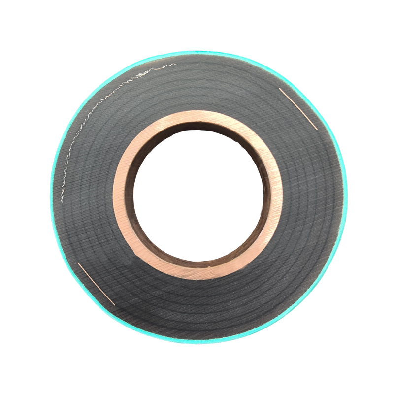
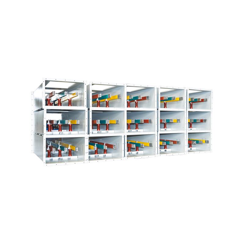
When the project needs a tested compact busway with a high fault rating, a compact busway system with verified joints is worth comparing against conventional designs.
 Compact Cast-Resin Busway for Low-Voltage DistributionThis low-voltage cast-resin busway uses a dense arrangement and epoxy insulation to save space while handling currents from 400 A to 5000 A. Its verified joints make it a practical option when comparing fault-rated busway designs.View Product →
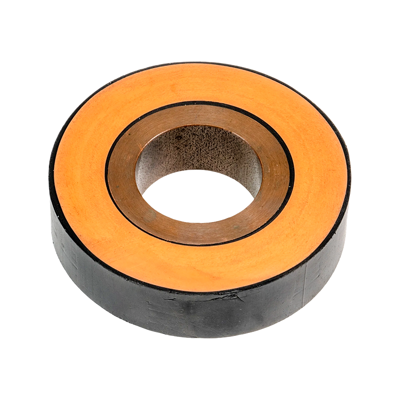
At medium voltage, a fully insulated tubular busbar with epoxy-resin casting reduces phase-to-phase spacing and gives a defined insulation limit during a short circuit, which makes the withstand calculation more predictable.
 Epoxy-Cast Tubular Busbar with Integrated InsulationThis fully insulated tubular busbar is formed by automated vacuum casting, giving a seamless conductor and shield structure. Its defined insulation behavior helps engineers predict short-circuit withstand at medium voltage.View Product →
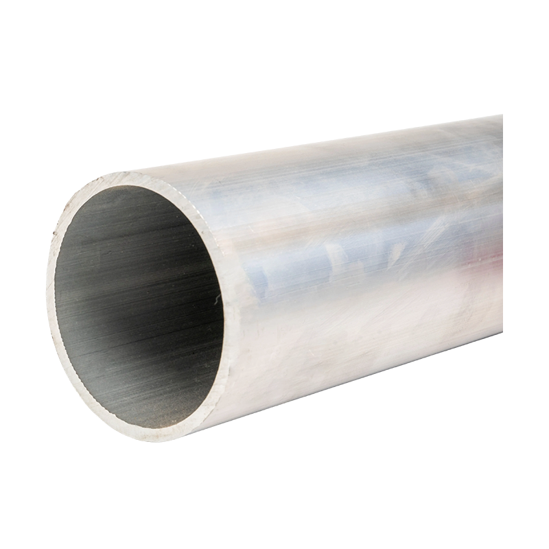
In extra-high-voltage substations, the conductor diameter, wall thickness, and support span of high-strength aluminum alloy tubular busbars are selected on the basis of both rated current and short-circuit force. If you are in the selection stage, how to choose the right bus bar for medium- and low-voltage systems covers the practical trade-offs.
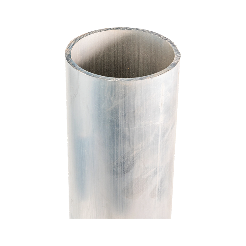 High-Strength Aluminum-Alloy Tubular Busbar for EHVBuilt for 220 kV to 1000 kV systems, this magnesium-aluminum alloy busbar combines high mechanical strength with reliable conductivity. Reviewing its fault-level ratings and type test reports supports confident selection for extra-high-voltage substations.View Product →
Share the fault-level study with the engineering team and ask for the corresponding type test report before production starts.
Frequently Asked Questions About Short-Circuit Withstand Ratings
What is the difference between Icw and Ipk?
Icw is the RMS current the busbar can carry for a stated duration without overheating. Ipk is the peak value of the first cycle of the fault, which creates the mechanical force. A 50 kA / 1 s busbar typically has an Ipk of 105 kA at 50 Hz.
Why do some ratings say 50 kA / 1 s and others 31.5 kA / 4 s?
The difference is the duration. One second suits low-voltage systems with fast breakers. Four seconds is common in medium-voltage systems where protection coordination can delay tripping. Doubling the duration doubles the I²t heating, so the conductor cross-section must be larger.
Can a busbar be reused after a real short circuit?
A busbar that has gone through a fault should be inspected even if it looks intact. Check bolted joints, insulator surfaces, and supports first. If an arc occurred, replace the affected insulation sections, because the material properties may have changed permanently.
Does a higher short-circuit rating always cost more?
Not proportionally. Increasing the conductor cross-section raises the rating, but a better joint design or a denser support arrangement can increase withstand capacity with less material. Compare the tested configuration, not only the label.
The short circuit withstand rating is the one number that separates a busbar that stays in service after a fault from one that disappears from the project in a single cycle. Read the complete value, including the duration and the peak current, and ask for the type test report behind it. When the fault level on site is higher than the rating, the consequences are not theoretical, so confirm the specification with the manufacturer before production begins.
Recommended Products



-
 +86-180 3625 3000
-
 admin@wpbusbar.com
-
 No. 8, Yanjin Road, Chengxi Industrial Park, Shanyang Town, Baoying County, Yangzhou City, Jiangsu Province, China
Copyright © Jiangsu Wopeng Power Technology Co., Ltd.
All Rights Reserved.
 Custom Insulated Bus Bar Manufacturer
Tubular Busbar System Factory
Custom Insulated Bus Bar Manufacturer
Tubular Busbar System Factory