

 EN

 English
 русский
 Français
 Español
 عربى

How to Design a Substation Busbar Layout: Schemes, Clearances and Spacing Rules
Content
- 1 The Inputs You Need Before Drawing Anything
- 2 Choosing the Busbar Arrangement Scheme
- 3 Clearances and Spacing Shape the Yard
- 4 Matching Conductor and Insulation to the Layout
- 5 Earthing, Maintenance Access and Room to Grow
- 6 A Practical Design Sequence
- 7 Where Busbar Layouts Usually Go Wrong
- 8 Frequently Asked Questions
The Inputs You Need Before Drawing Anything
Collect these before the first sketch. Missing any one of them pushes the problem into construction, where corrections cost far more than on paper.
- Nominal and highest system voltage, which set the insulation level and, indirectly, the geometry of the whole yard.
- Continuous bus current plus the growth the owner expects over the next 10 to 15 years.
- Short-circuit withstand: rms and peak current, and duration, typically 1 or 3 seconds.
- Site boundaries, existing rights of way, and the direction each line enters.
- Pollution level and altitude, both of which widen creepage and clearance requirements.
- Ambient temperature range, wind speed and seismic zone for structural loading.
- Redundancy rules: which circuits must keep running while a busbar or a breaker is maintained.
The last item decides money. A busbar carrying 800 A today is still designed for the 25 kA the network can deliver, because support spacing and insulator loading come from the peak short-circuit force rather than from the load current. Raise the fault level later and you rebuild the steel.
Choosing the Busbar Arrangement Scheme
The arrangement is a trade between switching flexibility and how many breakers, disconnectors and bays you buy, install and maintain over 30 years.
| Arrangement | Switching flexibility | Relative footprint | Typical fit | Main trade-off |
|---|---|---|---|---|
| Single busbar | Lowest; a bus fault or bus maintenance interrupts the station | Smallest | Small distribution substations, single-transformer sites | Simple and economical, but no bus maintenance window |
| Single busbar with sectionaliser | Moderate; sections can be isolated independently | Small | Distribution substations with two incoming feeders | Limits the outage, but does not remove it |
| Double busbar | High; any feeder can be transferred to either bus | Larger, with duplicated bus and extra disconnectors | Transmission nodes and important industrial substations | Higher cost and more complex interlocking |
| Main and transfer bus | Moderate; a feeder moves to the transfer bus for breaker maintenance | Slightly larger | Sites where breaker maintenance must not interrupt supply | Transfer switching demands strict procedure |
| One-and-a-half breaker | Highest; any breaker can be withdrawn without losing a circuit | Largest, with the most structures | EHV nodes and critical grid connections | Highest capital cost and protection complexity |
In practice, a single busbar with a sectionaliser covers most 10 kV to 35 kV distribution work. Double busbar earns its cost when losing the bus means losing production or a city district. One-and-a-half breaker arrangements belong at nodes where no circuit may be switched out to maintain a breaker.
Clearances and Spacing Shape the Yard
Once the arrangement is fixed, clearance is what actually draws the plan. Start from the highest system voltage, apply the pollution and altitude corrections, then check the result against the governing standard.
| System voltage | Typical minimum phase-to-phase clearance | Practical consequence for the layout |
|---|---|---|
| 10 kV | Around 200 mm | Compact bays; indoor switchgear often replaces open busbars |
| 35 kV | Around 400 mm | Slender bays, single-level busbar structures are common |
| 66 kV | Around 700 mm | Bay widths grow quickly; support structures become taller |
| 110 kV | Around 1000 mm | Two-level layouts with busbars above the disconnectors |
| 220 kV | Around 1800 mm | Long spans, heavy structures, wide access roads |
| 500 kV | Around 3800 mm | Yard planning is dominated by clearance and corona |
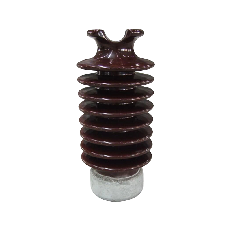
Two consequences follow. First, a 220 kV yard is roughly three times the width of a 35 kV yard carrying the same current. Second, span length matters as much as clearance. Post insulators commonly carry rigid tubular busbars on spans of 6 to 12 metres, and the span must be short enough that the peak short-circuit force does not overstress the insulator, the support, or the conductor itself.
Matching Conductor and Insulation to the Layout
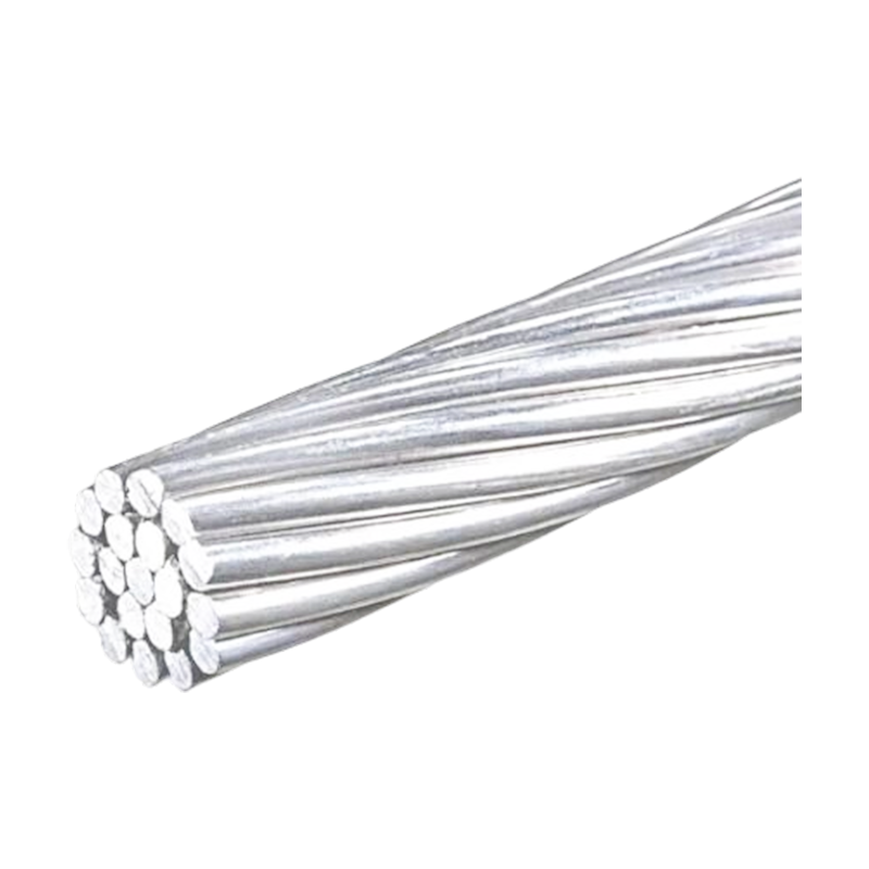
Conductor choice follows from the layout, not the other way around. Where clearances come easily, bare aluminium or copper tubular busbars on post insulators are the economical answer: rigid, easy to inspect, and simple to extend when a new bay is added.
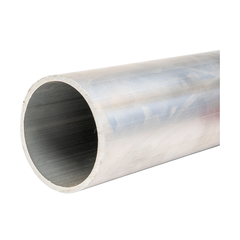 Aluminum Alloy Tubular Bus Bar for High-Voltage SystemsThis rigid 6063G aluminum alloy tubular busbar suits layouts with ample clearances, offering high mechanical strength and conductivity.View Product →
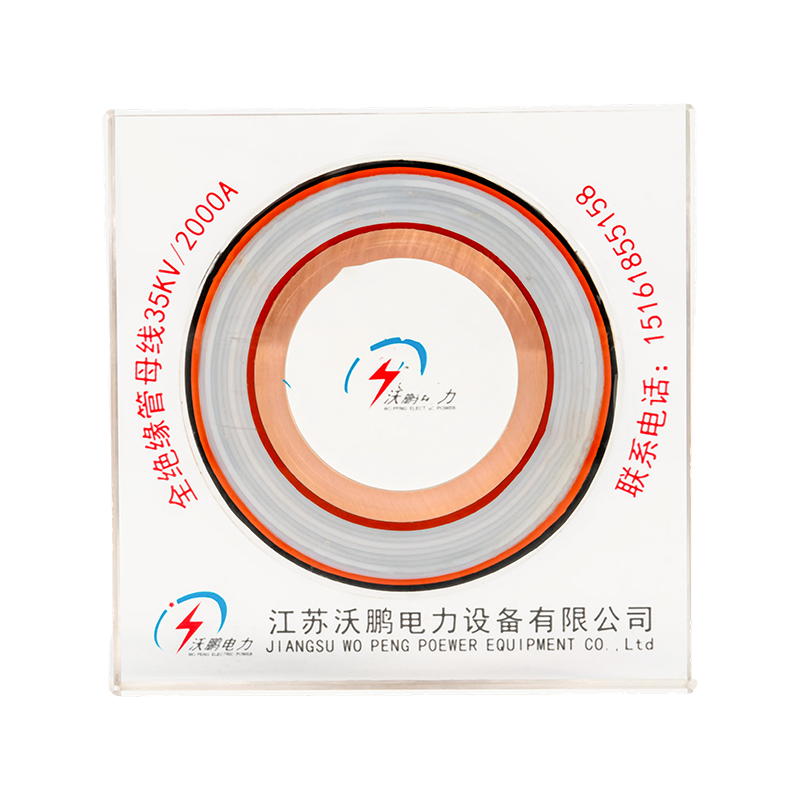
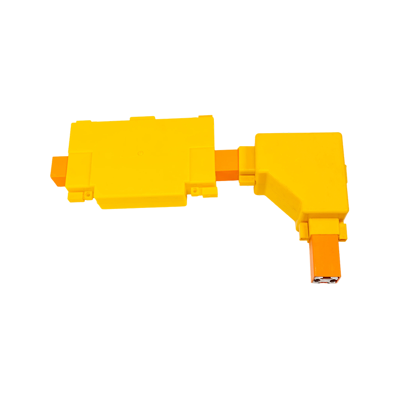
Where space is tight, such as an indoor switchgear room, a compact industrial bay, a wind turbine tower, a tunnel or a rooftop substation, bare conductors cannot meet clearance in the width available. Insulated tubular busbars solve that by putting the insulation on the conductor instead of relying on air, which is also why they are increasingly common in retrofit projects with fixed building dimensions. The fully insulated tubular bus bar range covers most of these constraints.
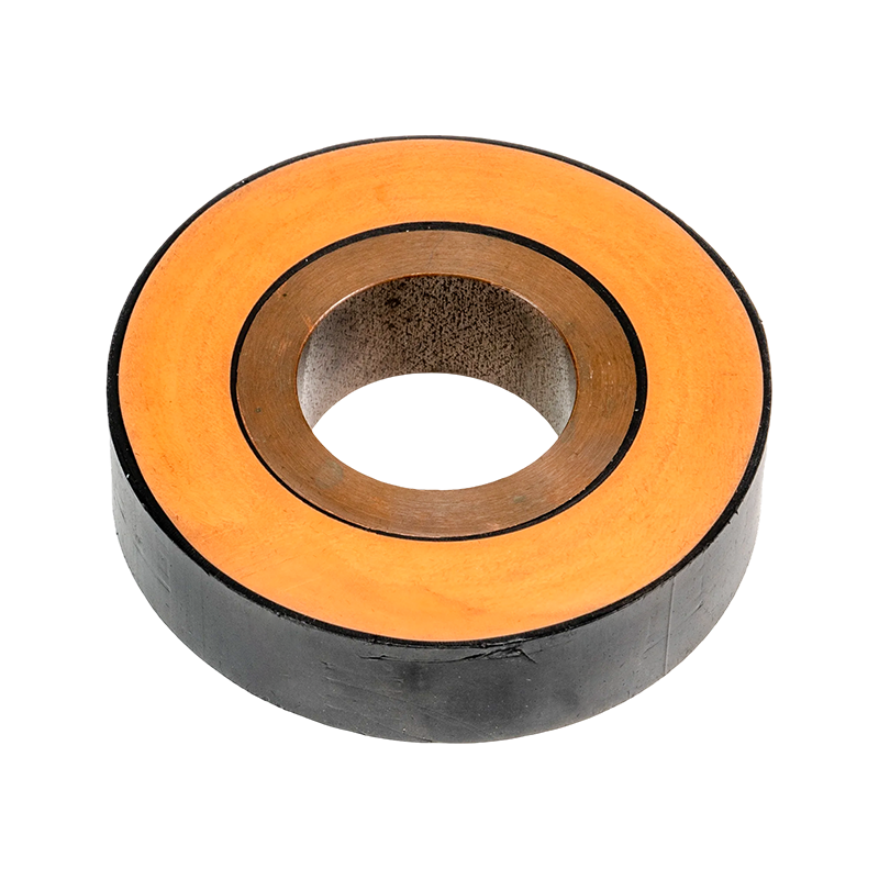
Three insulation systems handle most cases. Epoxy resin vacuum-cast busbars give a hard, dimensionally stable shell suited to humid or contaminated environments. EPDM silicone rubber keeps flexibility and absorbs thermal movement. PTFE suits applications where chemical resistance and a small diameter matter most.
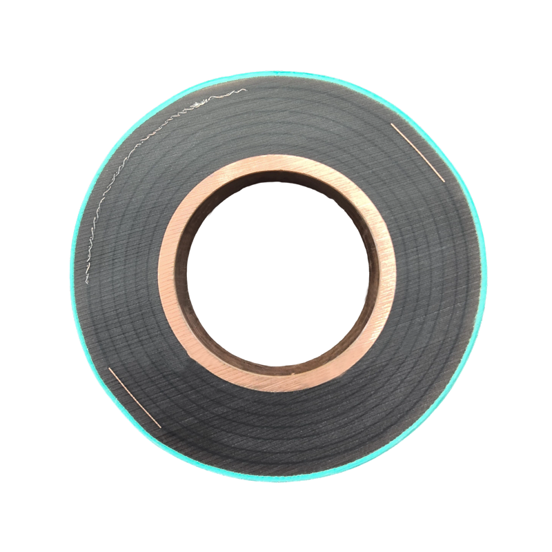 Fully Insulated Epoxy Resin Cast Tubular Bus BarThis fully insulated epoxy resin cast busbar provides a hard, dimensionally stable shell for humid or contaminated environments in medium and low voltage indoor use.View Product →
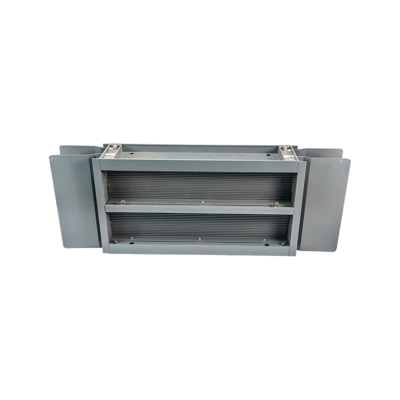
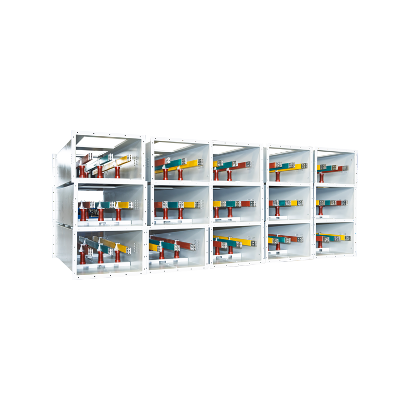
At medium and low voltage inside buildings, busway systems replace cable runs where tap-off flexibility, predictable heat dissipation and easier fault location matter more than the lowest first cost.
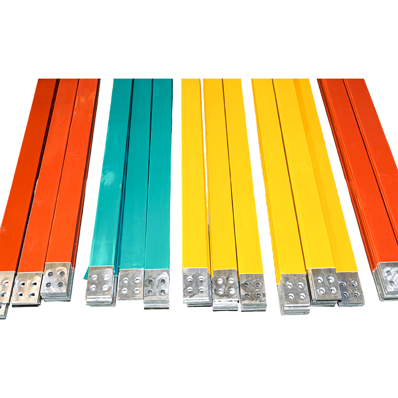 Fully Insulated High and Low Voltage Busway SystemThis fully insulated busway system offers a compact, shared-enclosure design for power distribution, suitable for retrofit and expansion projects with space constraints.View Product →
Earthing, Maintenance Access and Room to Grow
Busbar geometry and earthing design should move together. The earth grid footprint follows the conductor routes, so a busbar moved late in the design forces the earthing study to be redone, and step and touch voltage limits usually tighten rather than relax.
- Keep access roads 3.5 to 4 metres wide, with a clear turning area at the transformer bay.
- Leave enough walkway for a technician to operate disconnectors without entering the clearance zone.
- Route cable trenches so they do not cross under busbar supports that may need replacement.
- Reserve one spare bay or at least the physical space for it, including its earthing connections.
A Practical Design Sequence
- Confirm the electrical data: voltage, continuous current, fault level, and duration.
- Select the busbar arrangement from the redundancy requirement, not from habit.
- Derive clearances from the highest system voltage plus pollution and altitude corrections.
- Size the conductor for continuous current and short-circuit thermal duty.
- Set the span and support spacing from the peak short-circuit force.
- Place supports, foundations, roads and trenches on the plan, then check maintenance access.
- Verify protection zones, interlocking and earthing against the final physical layout.
- Review the drawing with the operations team before it is frozen; they will find the access problem you missed.
Where Busbar Layouts Usually Go Wrong
- Sizing the busbar for load current only, then discovering that support spacing is governed by fault force.
- Using a low-altitude clearance table on a site above 1000 metres.
- Forgetting that pollution level widens creepage, which lengthens insulators and raises structure heights.
- Placing a disconnector where the operating handle ends up inside the safety clearance.
- Leaving no physical room for a future bay, which later forces a full yard rearrangement.
- Choosing a flexible conductor where a rigid tubular busbar would have halved the span and the steel.



-
 +86-180 3625 3000
-
 admin@wpbusbar.com
-
 No. 8, Yanjin Road, Chengxi Industrial Park, Shanyang Town, Baoying County, Yangzhou City, Jiangsu Province, China
Copyright © Jiangsu Wopeng Power Technology Co., Ltd.
All Rights Reserved.
 Custom Insulated Bus Bar Manufacturer
Tubular Busbar System Factory