

 EN
EN

 English
 русский
 Français
 Español
 عربى
عربى


How to Calculate Busbar Current Rating: Practical Formula and Derating Guide
Content
On a recent 400 V switchboard upgrade, a contractor asked why a 50 × 10 mm copper busbar that looked fine on a 1000 A drawing was running at 78°C inside a closed cubicle. The busbar was not undersized by the basic formula, but the calculation had ignored ambient temperature, enclosure type, and the proximity of parallel bars. The short answer: busbar current rating is not a single number you read from a table. It is the result of a thermal calculation that starts with material, cross-section, and allowable temperature rise, then gets adjusted for real installation conditions. If you need a defensible rating for procurement or type testing, treat every derating factor as part of the design, not an afterthought.
The Core Formula: Start With Cross-Section, Then Derate
Most IEC and DIN-based calculations begin with a power-law relationship. For a rectangular bar, the steady-state current rating can be estimated as I = K × A^0.62 × ΔT^0.5, where A is the cross-sectional area in mm², ΔT is the permissible temperature rise above ambient in Kelvin, and K is a material and surface constant. This is the DIN 43671 form. It is not exact for every geometry, but it is close enough for early sizing and for checking vendor data.
For example, a copper bar with A = 500 mm² (50 × 10 mm) and ΔT = 55 K might calculate to around 1250 A in still air. The same cross-section in aluminum would be roughly 20–25% lower because aluminum has higher resistivity and lower thermal conductivity. That difference matters when a project changes from copper to aluminum late in the design. You cannot simply swap materials and keep the same rating.
The formula also assumes the bar is isolated. In a real busbar system, bars are mounted in enclosures, supported by insulators, and often run in parallel. Those conditions change both heat generation and heat dissipation. A calculation that stops at A and ΔT is a starting point, not a final answer.
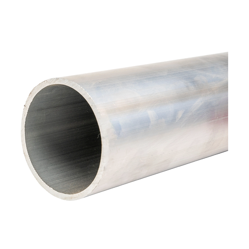
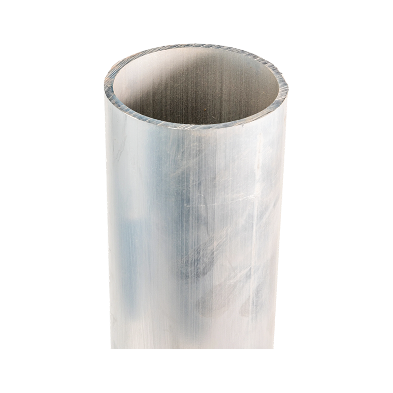 Ultra-High Voltage Magnesium-Aluminum Alloy Tubular Bus BarReview UHV tubular busbar options where alloy, profile, and real installation conditions affect current rating beyond cross-sectional area alone.View Product →
Material and Geometry Matter More Than the Number
Two busbars with the same cross-section can have different current ratings depending on shape, aspect ratio, and surface finish. A flat bar has more surface area per unit length than a round tube, so it dissipates heat differently. A tubular busbar with a larger diameter may carry more current at the same cross-sectional area because the perimeter is greater. This is why comparing only mm² is misleading.
Copper vs Aluminum: What Changes in the Calculation
Copper has a resistivity of about 1.72 × 10⁻⁸ Ω·m at 20°C, while aluminum is about 2.82 × 10⁻⁸ Ω·m. That is a 64% difference. For the same current, aluminum generates more heat. To keep the same temperature rise, you need roughly 25–30% more aluminum cross-section, or a lower ambient temperature, or better ventilation. In IEC 61439 assemblies, the design verification must account for the actual conductor material and temperature limit of the insulation.
Skin Effect and Proximity Effect at Higher Frequencies
At 50 Hz, skin effect in a 50 mm bar is modest, but it is not zero. For larger bars or higher frequencies, current crowds toward the surface, increasing effective resistance. Proximity effect between parallel bars makes it worse. A common rule for parallel bars is that two bars do not give twice the rating; expect 1.6 to 1.8 times the single-bar rating depending on spacing. Three bars may give 2.2 to 2.5 times. These multipliers are not a substitute for calculation, but they explain why nameplate ratings often look conservative.
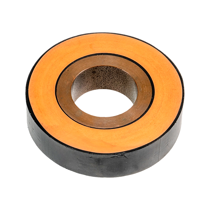
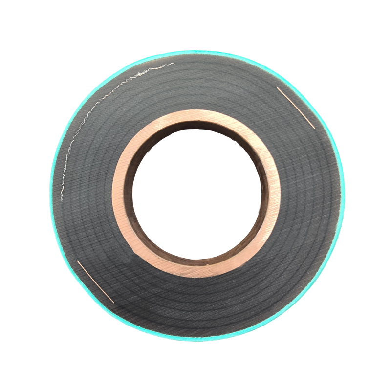 Epoxy Resin Casting Tubular Bus BarConsider this epoxy-cast tubular busbar for insulated medium/high-voltage runs, noting derating from ambient temperature, enclosure type, and altitude.View Product →
Derating Factors: Where Real Ratings Drop
The biggest gap between a calculated rating and a real installation is derating. Ambient temperature is the first factor. A bar rated at 40°C ambient may only carry 80–85% of that current at 55°C. Enclosure type matters too: a ventilated enclosure may allow 90% of open-air rating, while a sealed enclosure can drop it to 70% or less. Altitude above 2000 m reduces air density and cooling, so additional derating may be required.
The table below summarizes typical adjustments. Use it for sanity checks, not as a replacement for the manufacturer’s type test or a project-specific thermal study.
| Factor | Typical range | Effect on current rating |
|---|---|---|
| Ambient temperature above 40°C | 0.80–0.90 per +10°C | Lower permissible temperature rise |
| Sealed enclosure | 0.65–0.80 | Poor heat dissipation |
| Parallel bars (2 per phase) | 1.6–1.8 × single bar | Proximity effect and uneven sharing |
| Altitude above 2000 m | 0.90–0.95 per 1000 m | Reduced air density and convection |
| Harmonic current (THD > 15%) | 0.85–0.95 | Additional RMS heating and skin effect |
Notice that the table gives ranges, not exact values. The reason is that busbar rating depends on the specific enclosure, bar spacing, ventilation openings, and whether the bars are painted or bare. A black-painted bar can run cooler than a bare bar because it radiates heat better, but paint can also affect dielectric performance. That is a trade-off for the insulation system, not just the conductor.
A Step-by-Step Calculation Example
Suppose you need to verify a 1000 A low-voltage busbar in a 400 V switchboard. The ambient temperature is 35°C, the enclosure is ventilated, and the design allows a maximum conductor temperature of 105°C. That gives ΔT = 70 K. You plan to use a single copper bar, 50 × 10 mm.
- Calculate cross-sectional area: A = 50 × 10 = 500 mm².
- Estimate the base rating from I = K × A^0.62 × ΔT^0.5. For copper in still air, K is roughly 7.5 when A is in mm² and ΔT is in K. I = 7.5 × 500^0.62 × 70^0.5. 500^0.62 ≈ 45.5, 70^0.5 ≈ 8.37. I ≈ 7.5 × 45.5 × 8.37 ≈ 2850 A. This is higher than the 1000 A requirement, which is normal because the formula assumes open air and a 70 K rise.
- Apply enclosure and ventilation derating. For a ventilated enclosure, use 0.85. I ≈ 2850 × 0.85 ≈ 2420 A.
- Apply ambient correction. If the base ambient is 40°C and actual is 35°C, the correction is small: (105-35)/(105-40) = 70/65 = 1.08. But if actual ambient were 45°C, the allowable rise would be 60 K, and the rating would drop by about (60/70)^0.5 ≈ 0.93. I ≈ 2250 A.
- Check short-circuit withstand. The current rating is only half the story. The bar must also survive the prospective short-circuit current for 1 s without exceeding the permissible temperature. For copper, the adiabatic check is often S ≥ I_sc × √t / k, where k is around 143 for copper. A 1000 A bar may need a larger cross-section for a 50 kA fault than for normal current.
In this example, the bar is thermally adequate for 1000 A, but the final selection still depends on voltage drop, support spacing, and short-circuit forces. A common mistake is to size the bar for normal current and then discover that the support insulators cannot handle the peak fault force. That is a procurement risk: changing the bar size later can affect the entire busway layout.
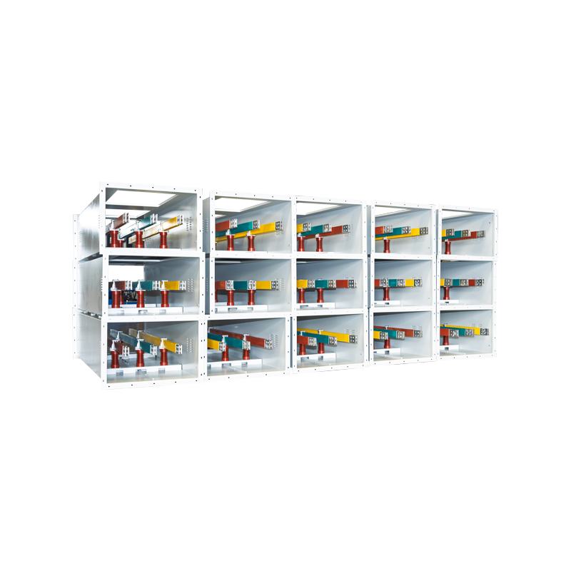
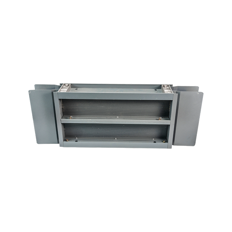 High-Density Compact Busway for Low-Voltage DistributionFor 0.4 kV distribution, this compact cast-resin busway supports high current with compact footprint and insulation, while fault-force and voltage-drop checks still govern selection.View Product →
Field Checks Before You Finalize the Rating
Calculations are necessary, but they are not sufficient. Before you approve a busbar rating, check the following:
- Torque and contact pressure at joints. A loose joint can add 10–20 K of local temperature rise even when the bar itself is correctly sized.
- Support spacing. Long unsupported spans can vibrate at 50 Hz and fatigue the conductor or insulators.
- Thermal imaging after load testing. A hot joint or a hot spot near an insulator indicates a problem that the calculation did not capture.
- Clearance and creepage distances. The rating is not valid if the insulation system cannot withstand the voltage.
- Documentation. Keep the calculation assumptions, derating factors, and test reports. If a consultant or inspector asks for the basis of the rating, you need to show it.
For medium- and low-voltage busways, the assembly standard IEC 61439-1 and IEC 61439-6 (busways) requires design verification by testing or by calculation. A calculation alone may be accepted for a custom design, but the responsibility for the result stays with the manufacturer. If you are comparing suppliers, ask for the type test report and the derating assumptions, not just the catalog ampacity. You can also read our guide on choosing the right bus bar for medium and low voltage applications for more selection criteria.
Frequently Asked Questions
Can I use the same formula for copper and aluminum?
You can use the same form, but K and the resistivity differ. Aluminum needs roughly 25–30% more cross-section for the same current and temperature rise. Always check the manufacturer’s data for the specific alloy and temper.
How much does a 10°C rise reduce busbar ampacity?
It depends on the base temperature. If you are already near the insulation limit, a 10 K increase can reduce the rating by 5–10%. If the bar is lightly loaded, the effect is smaller. The safest approach is to calculate with the worst-case ambient temperature, not the average.
Why do parallel bars not double the rating?
Because of proximity effect, uneven current sharing, and reduced surface area for cooling between bars. Two bars typically give 1.6–1.8 times the single-bar rating, and three bars give about 2.2–2.5 times. Use these as estimates only.
What standards should I reference?
For busbar ampacity calculations, DIN 43671 is widely used in Europe. For assemblies, IEC 61439-1 and IEC 61439-6 apply. In North America, IEEE 605 and NEC Article 368 are common references. If the project is in a specific country, check the local code because acceptable temperature limits and derating rules can differ.
So, how do you calculate busbar current rating? Start with the material and cross-section, apply the power-law formula, then subtract every real-world factor: ambient temperature, enclosure, altitude, harmonics, and parallel-bar effects. Verify the result with a short-circuit check and, where possible, a type test or thermal imaging. If you are still unsure about the right bar for your project, contact our engineers with your ambient temperature, fault level, and enclosure details. They can help you turn a rough calculation into a rating that will pass review and perform in the field.
Recommended Products



-
 +86-180 3625 3000
-
 admin@wpbusbar.com
-
 No. 8, Yanjin Road, Chengxi Industrial Park, Shanyang Town, Baoying County, Yangzhou City, Jiangsu Province, China
Copyright © Jiangsu Wopeng Power Technology Co., Ltd.
All Rights Reserved.
 Custom Insulated Bus Bar Manufacturer
Tubular Busbar System Factory
Custom Insulated Bus Bar Manufacturer
Tubular Busbar System Factory