

 EN
EN

 English
 русский
 Français
 Español
 عربى
عربى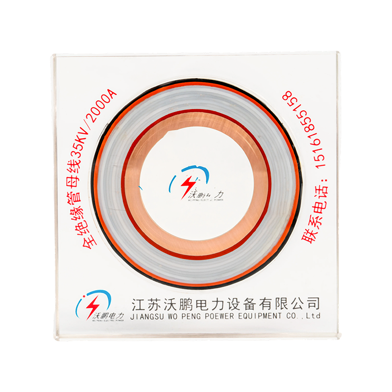
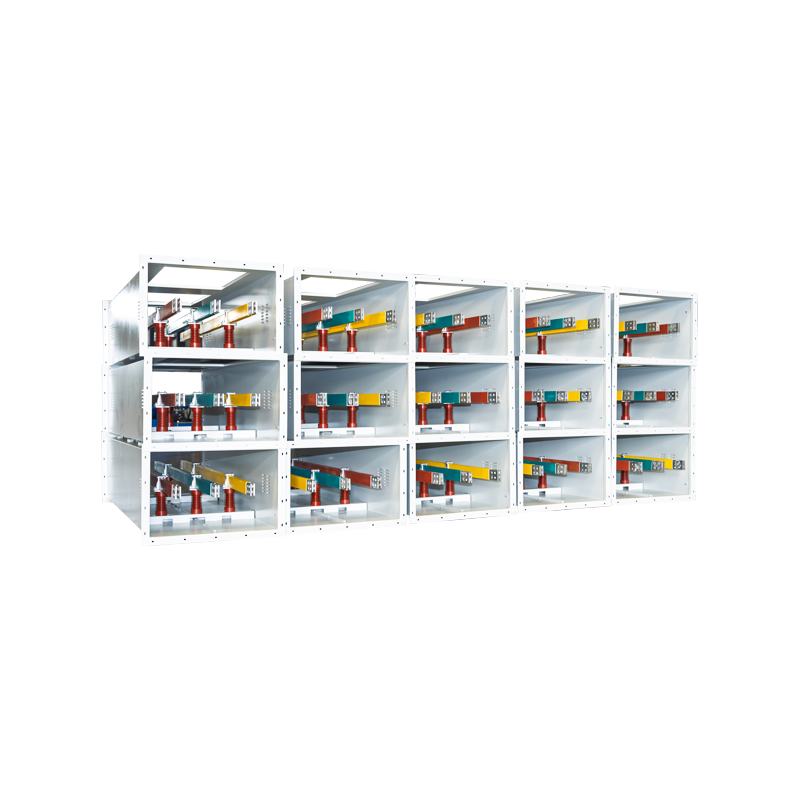


What is Medium-Low Voltage Bus Bar?
Content
- 1 What Is a Medium-Low Voltage Bus Bar?
- 2 How to Choose a Tubular Bus Bar System
- 3 Insulation Material Selection
- 4 Ultra-High Voltage Magnesium-Aluminum Alloy Tubular Bus Bar
- 5 Post Insulators and Bus-Bar Supports
- 6 High-Density Compact Busway Systems
- 7 Typical Application Scenarios
- 8 How to Select a Manufacturer and Supplier
What Is a Medium-Low Voltage Bus Bar?
A Medium-Low Voltage Bus Bar is a rigid conductor system rated for approximately 0.4 kV to 35 kV, used in substations, distribution rooms, industrial plants, and new-energy power stations to carry and distribute high currents. It replaces traditional cables, offering higher current-carrying capacity for the same cross-section while reducing line losses and installation footprint.
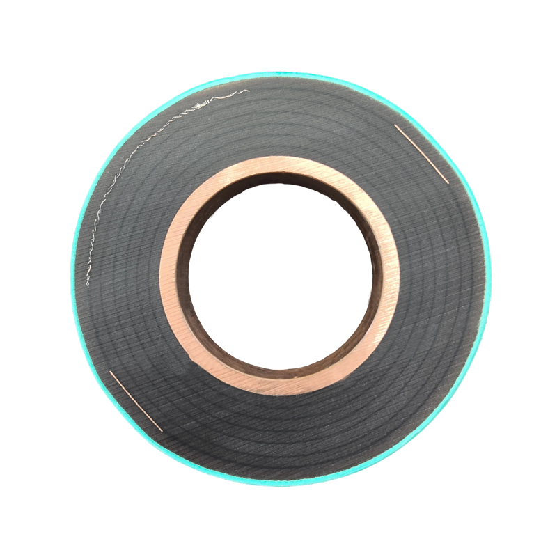
Common product forms include Fully Insulated Tubular Bus Bars, Aluminum Alloy Tubular Bus Bars, and ancillary components such as busbar connectors and post insulators.
| Voltage Class | Typical Values | Common Bus Bar Types | Typical Applications |
|---|---|---|---|
| Low Voltage | 220 V / 380 V / 690 V | Aluminum alloy tubular bus bar, insulated busbar | Industrial distribution cabinets, building power distribution |
| Medium Voltage | 10 kV / 20 kV / 35 kV | Fully insulated tubular bus bar, PTFE tubular bus bar | Substations, new-energy step-up stations |
| Extra-High Voltage Extension | Above 35 kV | Magnesium-aluminum alloy tubular bus bar | Large-span, long-distance transmission nodes |
How to Choose a Tubular Bus Bar System
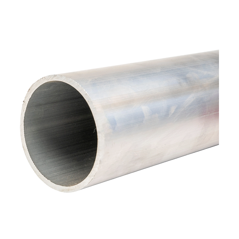
In a Tubular Busbar System, material determines current-carrying capacity, weight, and installation cost. Aluminum Bus Bars leverage low density, moderate conductivity, and cost advantages over copper, making them ideal for weight-sensitive overhead installations such as power plant outgoing lines and wind-farm step-up station connections.
Fully Insulated Tubular Bus Bars wrap the conductor with one or more insulation layers, significantly reducing phase-to-phase clearance. For example, a 2000 A rated aluminum tubular bus bar in an outdoor environment normally requires 300-400 mm phase spacing, whereas with full insulation this can be compressed to 150-200 mm, saving an entire row of equipment space in cramped urban substation retrofits.
Insulation Material Selection
Different insulation processes correspond to different temperature, weather, and mechanical performance levels, directly affecting service life and applicable environments.
| Insulation Type | Temp. Range (Reference) | Applicable Environment | Key Advantages |
|---|---|---|---|
| PTFE Tubular Bus Bar | Approx. -60 C to 200 C+ | High-temperature, chemically corrosive environments | High-temperature resistance, chemical corrosion resistance, high dielectric strength |
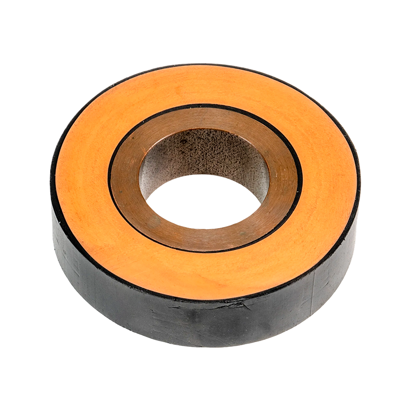
| Epoxy Resin Casting Tubular Bus Bar | Approx. -40 C to 120 C | Indoor switchgear, compact layouts | High mechanical strength, smooth surface, moisture and dust resistance |
| EPDM Silicone Rubber Tubular Bus Bar | Approx. -50 C to 150 C | Outdoor, humid, salt-spray regions | Strong weather resistance, anti-aging, elastic and crack-resistant |
PTFE manufacturers typically customize for high-temperature operations such as metallurgy and chemical plants, while EPDM silicone rubber suppliers focus on coastal or outdoor projects because EPDM ages far more slowly than ordinary PVC under long-term UV and moisture exposure. Epoxy resin casting is common in compact indoor switchgear due to its hard, easy-to-clean surface.
Ultra-High Voltage Magnesium-Aluminum Alloy Tubular Bus Bar
By adding magnesium and other alloying elements to traditional aluminum, Magnesium-Aluminum Alloy Tubular Bus Bars achieve higher tensile strength and corrosion resistance. Compared with pure aluminum, they are lighter and more rigid for the same cross-section, allowing wider support spacing in long-span, high-wind, or seismic zones, thereby reducing the number of post insulators and overall project cost.
For 35 kV+ applications, when selecting a manufacturer, focus on:
- Alloy ratio and surface oxidation treatment processes
- Mechanical calculation reports for large-span design
- Capability to provide integrated ultra-high-voltage busbar system solutions
Post Insulators and Bus-Bar Supports
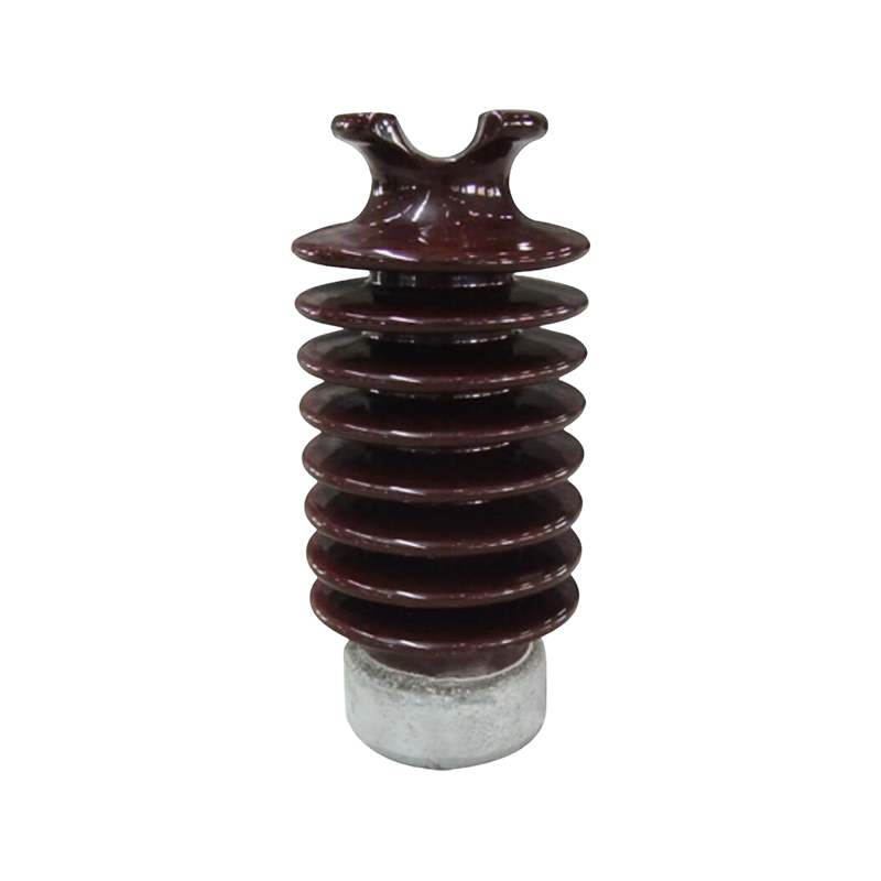
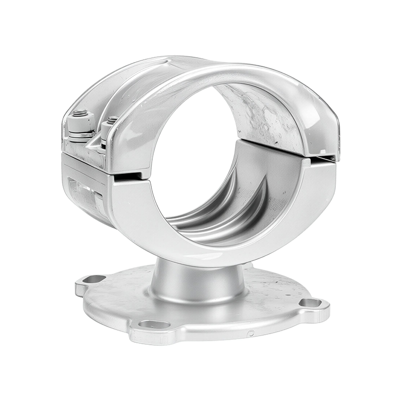
A complete bus bar system relies on Post Insulators and Bus-Bar Supports. Post insulators fix the bus bar to floors, walls, or frameworks while providing ground insulation. Supports constrain phase spacing and mechanical vibration, preventing displacement or collision under short-circuit current impact.
Support selection must account for bus-bar self-weight, short-circuit electrodynamic forces, and thermal expansion. For instance, a 6 m aluminum tubular bus bar experiencing a 40 C temperature swing may elongate several millimeters axially; supports therefore typically include sliding gaps to avoid additional thermal stress.
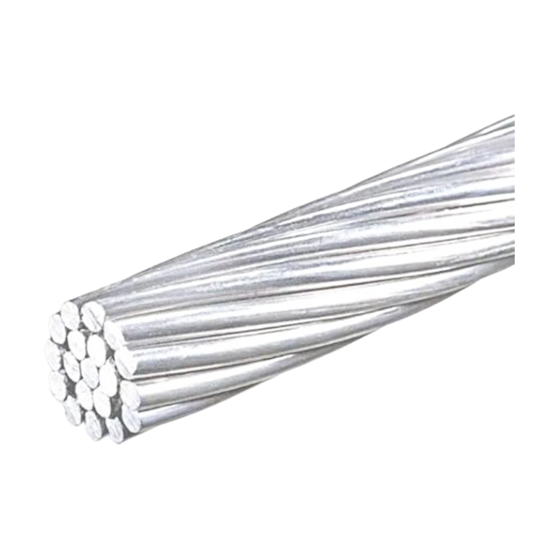
When selecting a Bus-Bar Supports Manufacturer, request short-circuit electrodynamic force calculation data to ensure the support fails only after the bus bar itself. Additionally, Reinforcing Steel Aluminum Strand is commonly used for flexible connections between bus bars and equipment terminals, compensating for installation tolerances and thermal expansion while maintaining high current capacity.
High-Density Compact Busway Systems
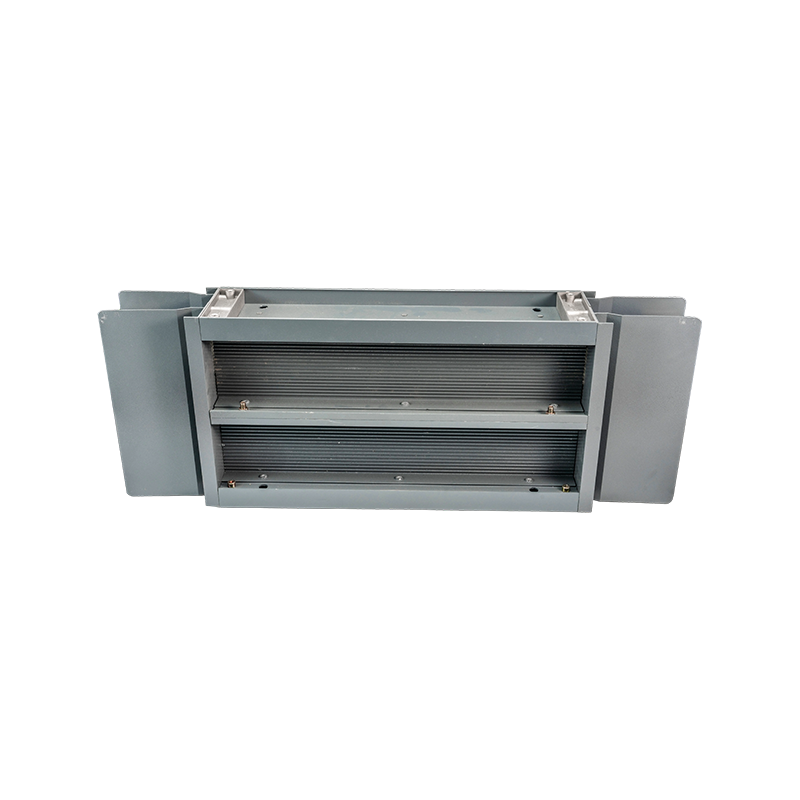
In data centers, commercial buildings, and modern industrial plants, High-Density Compact Busway is gradually replacing traditional cable runs. For the same current rating, busway occupies roughly one-third the cross-sectional area of an equivalent cable bundle, critical for projects with limited floor height or tight vertical shaft space.
High And Low Voltage Busway Systems are classified by voltage and rated current, commonly covering several hundred amperes up to 6300 A or more. When selecting a supplier, verify:
- Short-circuit withstand test certification
- Enclosure protection rating such as IP54 or IP65 for dust and water resistance
- Availability of overall system configuration recommendations
Typical Application Scenarios
Electrical busbar systems cover the following scenarios:
- Substation connections between main transformers and switchgear
- High-current links between inverters and step-up stations in PV and wind farms
- Industrial plant connections for high-power motors, VFDs, and distribution cabinets
- Data-center UPS-to-PDU high-current busbar wiring
- Building low-voltage distribution branching and busing
In these scenarios, busbar connectors ensure reliable electrical continuity between bus bar sections and equipment terminals. A well-designed connector must balance contact resistance, mechanical fastening strength, and temperature rise, typically keeping temperature rise within 60 K to 70 K under rated current. Proper electrical busbar insulation at connection points further reduces ground discharge risk.
How to Select a Manufacturer and Supplier
When evaluating a Medium And Low Voltage Bus Bar Manufacturer, consider the following dimensions:
- Certifications and Standards: IEC or GB type-test reports, especially short-circuit withstand tests
- Material Traceability: Alloy composition reports ensuring conductivity and mechanical performance
- Customization: Ability to provide custom busbar solutions, including non-standard arcs and special interfaces
- Insulation Process Maturity: Insulation thickness and withstand-voltage test data from PTFE or epoxy resin casting suppliers
- Ancillary Supply: Synchronized provision of post insulators and bus-bar supports to reduce multi-vendor coordination
- Delivery and After-Sales: Installation guidance and on-site technical support for critical components



-
 +86-180 3625 3000
-
 [email protected]
-
 No. 8, Yanjin Road, Chengxi Industrial Park, Shanyang Town, Baoying County, Yangzhou City, Jiangsu Province, China
Copyright © Jiangsu Wopeng Power Technology Co., Ltd.
All Rights Reserved.
 Custom Insulated Bus Bar Manufacturer
Tubular Busbar System Factory
Custom Insulated Bus Bar Manufacturer
Tubular Busbar System Factory