


 EN
EN

 English
 русский
 Français
 Español
 عربى
عربى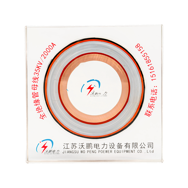
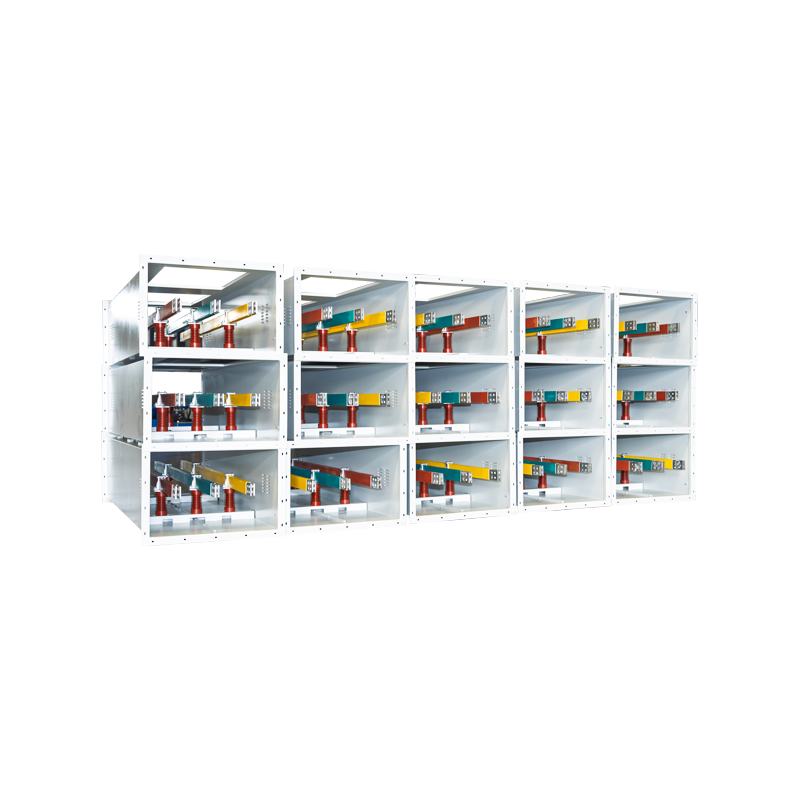

A high and low voltage busway system is the engineering benchmark for large-scale power distribution — replacing cable-and-conduit runs with factory-engineered enclosed conductors that carry from below 600V to beyond 230kV. Compared to traditional wiring, busway systems deliver shorter installation schedules, lower voltage drop, and superior expansion flexibility. This article provides a complete decision framework: insulation technology, material selection, structural performance, and application-specific solutions.
System Definition and Voltage Classification
NEMA defines a busway as a prefabricated electrical distribution system consisting of bus bars in a protective enclosure, including straight lengths, fittings, devices, and accessories. The electrical busbar system transports power from transformers to switchgear, panelboards, and downstream equipment — delivering structured, modular power flow as an alternative to individually pulled conductors.
ANSI standards classify voltage into three primary tiers: low voltage (up to 600V), medium voltage (600V to 69kV), and high voltage (69kV to 230kV), with extra-high and ultra-high voltage defined separately. This classification drives every downstream decision — insulation material, conductor cross-section, enclosure rating, and creepage distance requirements.
Three Core Insulation Technologies
The long-term reliability of a fully insulated tubular bus bar depends directly on insulation material selection. Each technology offers a distinct balance of dielectric strength, thermal rating, chemical resistance, and service life — and the wrong choice in a demanding environment is difficult and expensive to remediate after installation.
Polytetrafluoroethylene provides near-universal chemical inertness and outstanding dielectric strength. A custom PTFE tubular bus bar manufacturer engineers these systems for corrosive environments, semiconductor fabrication, and pharmaceutical facilities where long-term insulation integrity cannot be compromised. PTFE insulated tubular busbar suppliers typically offer custom wall thickness and length configurations.
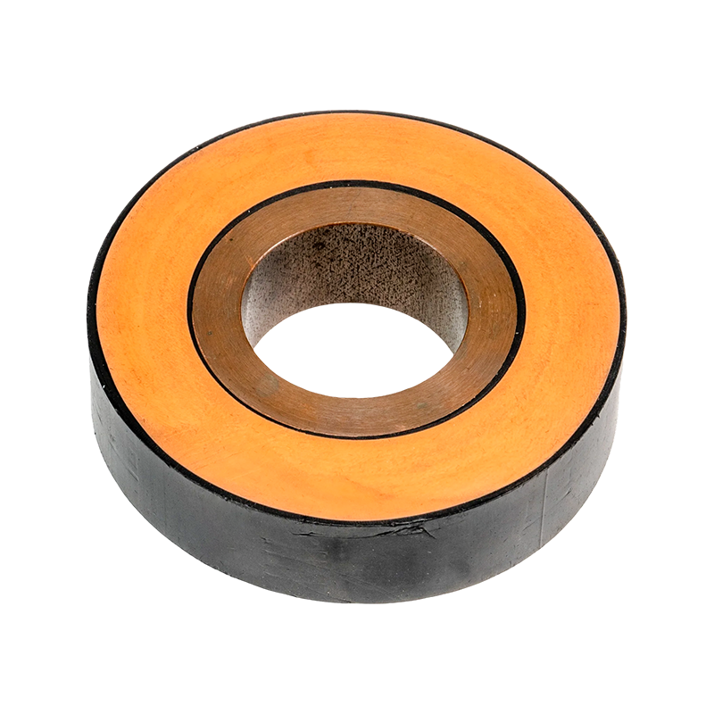
The conductor is fully encapsulated in epoxy resin, forming a solid insulating body with superior mechanical strength and moisture resistance. Epoxy resin casting tubular bus bar suppliers offer temperature classes from B (130°C) through F (155°C), making this technology the standard choice for medium-voltage switchgear and outdoor substation applications.
EPDM silicone rubber insulated busbar manufacturer products leverage a wide operating temperature range (-60°C to +200°C) and UV aging resistance for high-voltage outdoor applications. High voltage EPDM silicone rubber tubular bus bar systems have validated over 25 years of reliable service life in 220kV substations and coastal industrial facilities.
Tubular Busbars vs. Flat Bar: Measurable Performance Differences
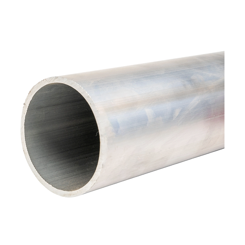
A tubular busbar system outperforms flat rectangular busbars across three measurable dimensions. The hollow tube geometry exploits the skin effect, concentrating AC current along the outer surface and reducing effective resistance. Internal airflow provides passive cooling, lowering operating temperature at equivalent current density. The circular cross-section delivers isotropic mechanical resistance against the electromagnetic forces generated during short-circuit events.
The aluminum bus bar has become the dominant conductor material for medium- and high-voltage tubular systems. At roughly one-third the density of copper and 61% of copper's IACS conductivity rating, aluminum achieves equivalent ampacity at a larger cross-section while reducing overall system weight by more than 40%. Ultra-high voltage magnesium-aluminum alloy tubular bus bar manufacturer technology extends this advantage to 220kV and above, where the magnesium-aluminum alloy busbar supplier's products offer critical strength-to-weight improvements for long-span configurations.
High-Density Compact Busway: How the Sandwich Structure Works
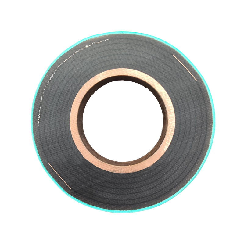
The high-density compact busway is the industry standard for high-current applications. Its defining characteristic is the sandwich construction: conductors wrapped with Class B polyester film coated with epoxy or polypropylene insulating material are stacked inside a metal housing with no air gaps between layers — fundamentally different from air-insulated busway where conductors are separated by open air spaces.

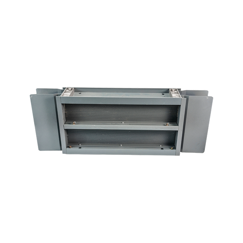
Pictured is a finished high and low voltage busway system unit featuring aluminum alloy or copper conductors encapsulated in multi-layer insulation and housed within a high-strength metal enclosure. The system delivers outstanding current-carrying capacity and short-circuit withstand performance, suited for industrial plant main feeders, high-rise vertical riser distribution, and data center high-current backbone applications. The enclosure — manufactured from heavy-gauge steel or aluminum alloy — achieves up to IP54 protection, and the system supports both plug-in and bolt-on branch access configurations across current ratings from 400A to 6300A.
High-density compact busway systems are manufactured from 400A and scale to 6300A, serving as the engineering standard for factory main feeders, high-rise vertical risers, and data center backbone power distribution.
Busway vs. Cable and Conduit: The Engineering Data
| Evaluation Dimension | Busway System | Cable and Conduit |
|---|---|---|
| Installation speed | Modular bolt-together sections; shorter schedule | Pull wires through conduit; more labor-intensive |
| System voltage drop | Lower (solid conductors, reduced impedance) | Higher than equivalent busway run |
| Space requirement | Compact cross-section; minimal tray volume | Multiple parallel cables occupy greater volume |
| Expansion flexibility | Plug-in units added live without shutdown | Re-pull cables required; outage needed |
| Initial material cost | Higher upfront | Lower initial cost |
| Lifecycle cost | Lower overall (reduced losses and maintenance) | Higher long-term operating expense |
Bus-bar Supports and Post Insulators: The Structural Foundation
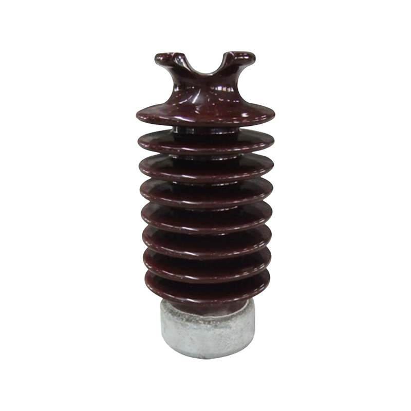
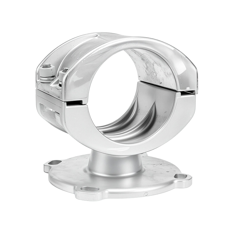
Reinforced busbar support systems and post insulators are critical to long-term busway reliability. Under high-current and short-circuit conditions, electromagnetic forces on bus conductors can reach tens of times the normal operating load. Insulated bus-bar supports manufacturer products must sustain these dynamic loads without fatigue cracking or connection loosening that leads to contact degradation over time.
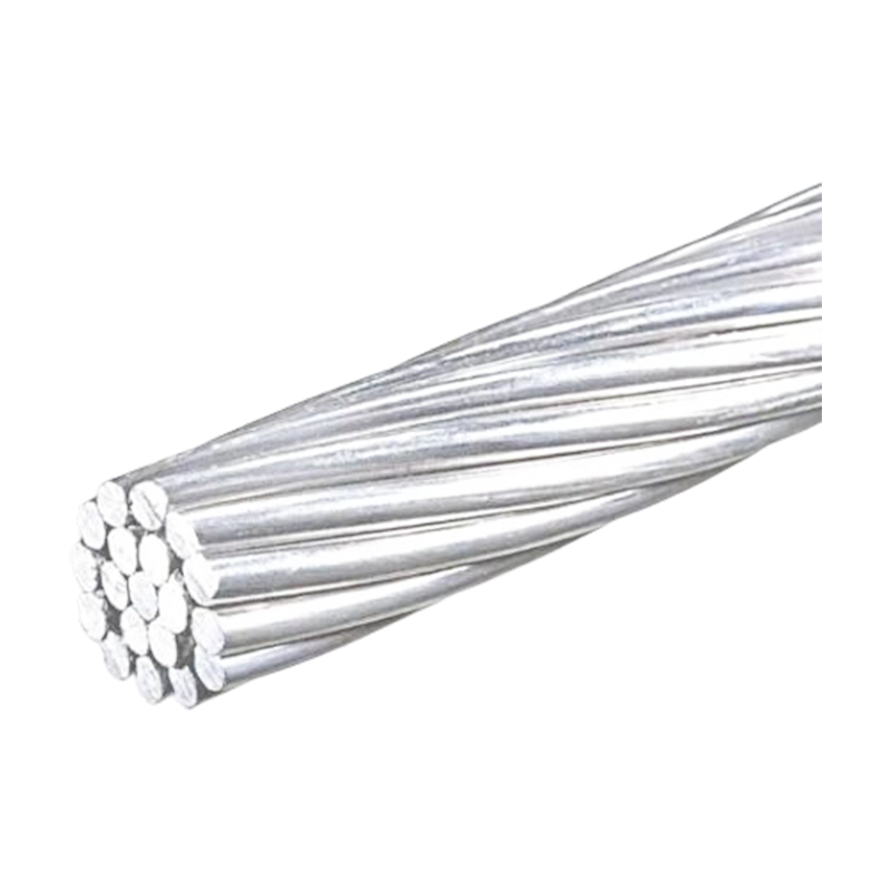
High-voltage post insulator manufacturer products must satisfy creepage distance requirements appropriate to system voltage: low-voltage systems typically require a minimum of 25mm/kV, while high-voltage post insulator manufacturer specifications comply with IEC 60305 and equivalent national standards at significantly more stringent pollution class levels. Reinforcing steel aluminum strand, produced by reinforced aluminum strand suppliers to custom tensile specifications, strengthens overhead busbar spans and long-distance aerial configurations where conductor sag and wind-induced vibration must be controlled within defined limits.
Application Scenarios and Busway System Solutions
Plug-in compact busway rated 800A to 4000A supports live addition or relocation of branch units. Track busway provides continuous tap-off access along the entire run, accommodating frequent rack layout changes without planned outages.
High current busbar systems from 630A to 6300A serve as main feeders. Plug-in tap boxes supply machine tools directly from the busway run, eliminating secondary wiring and significantly reducing plant reconfiguration cost.
Low-voltage electrical busbar systems in vertical risers distribute transformer output floor by floor, saving approximately 30% of shaft space compared to conventional riser cables while enabling per-floor capacity expansion.
Isolated-phase and segregated-phase busway configurations at generation and transmission level use high voltage EPDM silicone rubber tubular bus bar and ultra-high voltage magnesium-aluminum alloy busbar systems compliant with IEC 62271 and GB/T 5585.
Custom Busbar Solutions: Key Technical Parameters
Specifying a high and low voltage busway system requires defining the following parameters at the design stage. Each parameter drives downstream engineering decisions that are difficult and costly to change after installation begins.
When sourcing, prioritize medium and low voltage bus bar manufacturers and aluminum alloy tubular bus bar manufacturers who provide complete type-test documentation per IEC, UL 857, or applicable GB/T standards, along with factory acceptance test records traceable to a certified quality management system.