

 EN
EN

 English
 русский
 Français
 Español
 عربى
عربى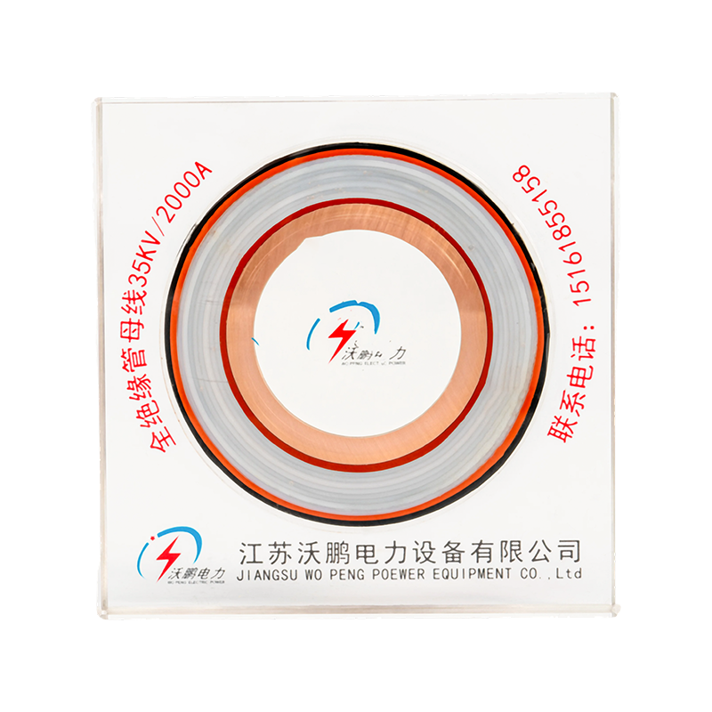


How to Select Medium-Low Voltage Bus Bar Specifications?
Content
- 1 Step 1: Identify the Voltage Class of the Network
- 2 Step 2: Size the Rated Current, Not Just the Nameplate Load
- 3 Step 3: Choose Between Copper and Aluminum Conductors
- 4 Step 4: Confirm the Insulation System
- 5 Step 5: Verify Short-Circuit Withstand and Mechanical Support
- 6 Step 6: Match Protection Rating to the Installation Environment
- 7 Step 7: Confirm the Manufacturer's Compliance and Track Record
- 8 Frequently Asked Questions
The correct specification for a medium and low voltage bus bar is fixed by four numbers in this order: system voltage class, rated current under peak load, short-circuit withstand current, and ambient protection rating. Get the voltage class wrong and insulation fails; get the current wrong and the conductor overheats; get the short-circuit rating wrong and a fault destroys the installation. Everything else in the selection process — conductor material, insulation type, support spacing, enclosure rating — is derived from these four values.
Step 1: Identify the Voltage Class of the Network
Every insulated bus bar is designed around a specific voltage band, and mixing bands is the single most common specification error. Low-voltage electrical busbar systems are rated up to 1kV AC and rely on air gaps, heat-shrink sleeves, or molded housings for insulation. Medium-voltage tubular busbar systems cover 1kV to roughly 36kV and need engineered insulation — epoxy resin casting, wrapped tape, or gas-filled enclosures — capable of holding off impulse voltages that can reach 170kV during switching transients. A 35kV wrapped-insulation busbar and a 0.4kV epoxy-cast busbar are not interchangeable even if the physical conductor size looks similar.
| Parameter | Low Voltage (0.4kV) | Medium Voltage (10–35kV) |
|---|---|---|
| Insulation method | Epoxy casting, air, molded | Epoxy casting, wrapped tape |
| Rated current range | 1000–8000A | 1000–8000A |
| Temperature rise limit | Below 30K | Below 30–45K |
| Governing standard | DL/T 1658-2016 | DL/T 5789-2019 |
| Typical use case | Industrial distribution, data centers | Substations, wind-solar booster stations |
Step 2: Size the Rated Current, Not Just the Nameplate Load
A high current busbar must be selected for the peak sustained load plus a margin for future expansion, not the average daily draw. Rated currents on the full 0.4–35kV series typically span 1000A to 8000A, built around high-purity T2 copper tubular conductors that keep the temperature rise under 30K on the low-voltage series and under 45K on the 35kV series. Because a tubular conductor spreads current across a hollow cross-section rather than a solid bar, skin effect losses drop significantly at high frequency and high amperage compared with flat busbar of the same rating, which is why tubular geometry dominates in installations above 2000A.
- Below 1000A: laminated or flat aluminum bus bar is usually sufficient and cost-effective
- 1000–4000A: tubular copper or aluminum with epoxy casting becomes the standard choice
- 4000–8000A: full tubular design with capacitive screen voltage grading is required for stable field distribution
Step 3: Choose Between Copper and Aluminum Conductors
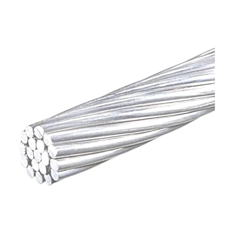
Copper delivers roughly 98% IACS conductivity and remains the default choice where panel space is limited, since it needs a smaller cross-section to carry the same current. Aluminum bus bar is lighter and lower in material cost, but a designer switching from copper must plan for 50–60% more cross-sectional area to reach equivalent ampacity — a factor that affects enclosure width, support spacing, and total installed weight on long busway runs. For overhead or wind-power booster applications where weight matters more than footprint, reinforcing steel aluminum strand construction is often specified instead of solid aluminum bar to add mechanical tensile strength without a large conductivity penalty.
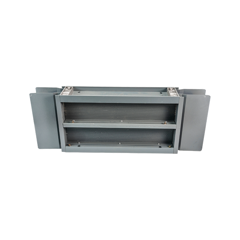
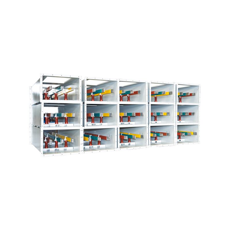
Once the voltage class and conductor sizing are settled, it helps to see how a supplier's product range maps onto these choices — the busway and support hardware below all serve directly into the 0.4–35kV specification range discussed above.
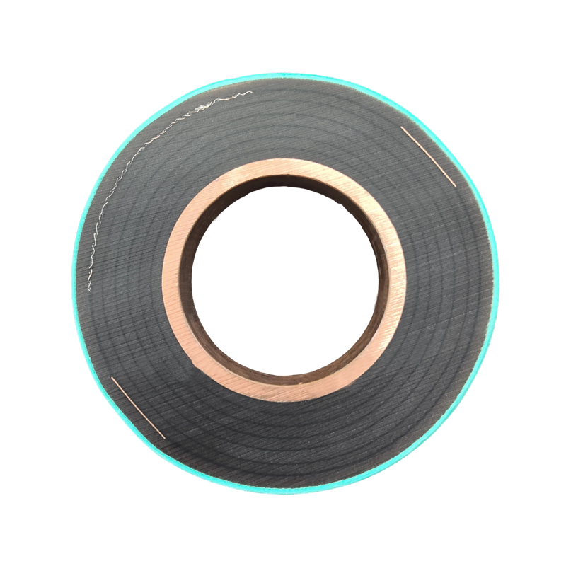
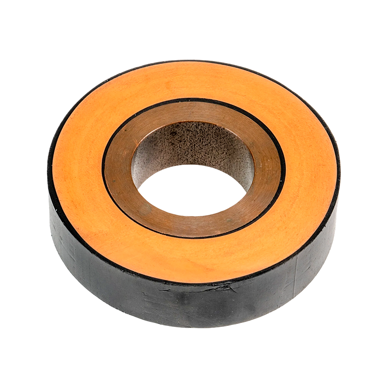
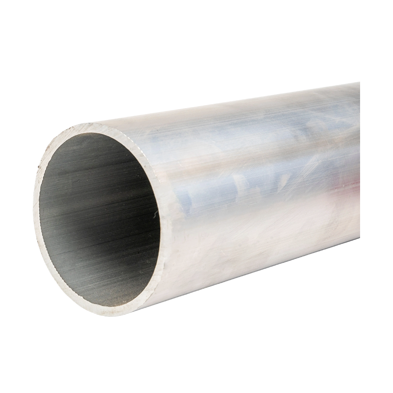
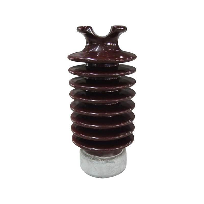
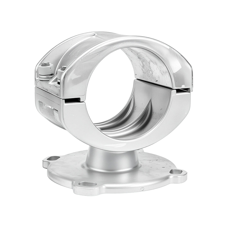
A representative selection of tubular busway and insulation systems engineered for the 0.4–35kV current path, from compact indoor runs to fully insulated outdoor installations.





Step 4: Confirm the Insulation System
A fully insulated tubular bus bar typically uses one of three materials, and the choice changes both cost and environmental tolerance. Epoxy resin casting bonds a rigid insulation shell directly to the conductor, giving strong dielectric performance and a compact outer diameter, which suits indoor substations and switchgear rooms. EPDM silicone rubber insulation stays flexible across a wider temperature band and resists UV and ozone degradation better, making it the common pick for outdoor and coastal installations. PTFE tubular bus bar insulation offers the highest thermal class of the three and is reserved for applications where ambient temperatures or continuous current push conductor temperatures toward the upper end of the rating.
Step 5: Verify Short-Circuit Withstand and Mechanical Support
The busbar and its support structure must survive a fault without permanent deformation. Reliable systems are rated to withstand 50kA to 100kA of fault current for the standard clearing time without displacement of the conductor from its supports. Bus-bar supports and post insulators are specified alongside the conductor, not as an afterthought — span length, wind load (for outdoor runs), and seismic zone all affect how many support points a given current rating needs. As a rule, longer unsupported spans require insulators rated for higher cantilever load, and any busway system solutions proposal should list support spacing explicitly rather than leaving it to field installation.
Step 6: Match Protection Rating to the Installation Environment
Indoor panels can typically use IP20 to IP40 enclosures. Busway routed through mechanical or electrical rooms with dust or moisture exposure should move to IP54 or higher, and any outdoor or coastal run should specify IP66 as the floor, not the ceiling. A high-density compact busway installed outdoors without adequate sealing will see accelerated insulation aging regardless of how well the conductor itself was sized.
Step 7: Confirm the Manufacturer's Compliance and Track Record
Before ordering, request type-test reports for temperature rise and short-circuit withstand, along with ISO certification and compliance evidence against DL/T 1658-2016 and DL/T 5789-2019 or the equivalent IEC standard for the destination market. A manufacturer offering custom busbar solutions should also be able to show completed projects in a similar voltage class and current range — substation, wind-solar booster station, or data center references carry more weight than generic catalog claims.
Frequently Asked Questions
How long does a properly specified bus bar system last?
A correctly sized and installed system typically runs 30 to 40 years with only routine inspection, provided the current rating was not exceeded during its service life.
Can aluminum fully replace copper in a high current busbar?
Yes, but the aluminum conductor needs 50 to 60 percent more cross-sectional area than copper to reach the same ampacity, which increases the physical footprint of the run.
What temperature rise should a joint be designed for?
Conductor bodies are generally limited to a rise of 30 to 45K depending on voltage class, while bolted or clamped joints are commonly capped at 105 degrees Celsius absolute temperature.
Is a cast resin busbar suitable for humid or coastal sites?
Yes. Fully insulated, waterproof cast resin construction is largely maintenance-free and is a common choice specifically because it tolerates harsh outdoor and coastal environments well.



-
 +86-180 3625 3000
-
 admin@wpbusbar.com
-
 No. 8, Yanjin Road, Chengxi Industrial Park, Shanyang Town, Baoying County, Yangzhou City, Jiangsu Province, China
Copyright © Jiangsu Wopeng Power Technology Co., Ltd.
All Rights Reserved.
 Custom Insulated Bus Bar Manufacturer
Tubular Busbar System Factory
Custom Insulated Bus Bar Manufacturer
Tubular Busbar System Factory