

 EN

 English
 русский
 Français
 Español
 عربى
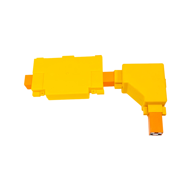

How to Install a Tubular Bus Bar: A Step-by-Step Guide for Field Crews
Content
A crew arrives at a collector substation with a dozen aluminum tubes, a crate of clamps and one day before the bay is scheduled for energization. Lifting the tubes takes about an hour. The rest of the day disappears into support alignment, joint preparation, torque checks and clearance measurements — and that is exactly where tubular bus bar installations succeed or fail.
The short version: erect and align the supports and insulators first, seat the tubes, prepare and torque every joint, leave room for thermal expansion, then verify clearances, insulation resistance and contact resistance before anyone energizes the circuit. Tube quality matters, but field failures usually trace back to support spacing, joint contact quality and expansion allowance.
Before the First Tube Goes Up
Most of a clean installation is decided while the bay is still de-energized. Work through this list before mobilizing the lifting crew:
- Lock out and tag out the circuit, verify the absence of voltage and apply temporary grounds.
- Compare the drawing with reality: actual span between structures, base plate positions, and whether the steelwork is plumb.
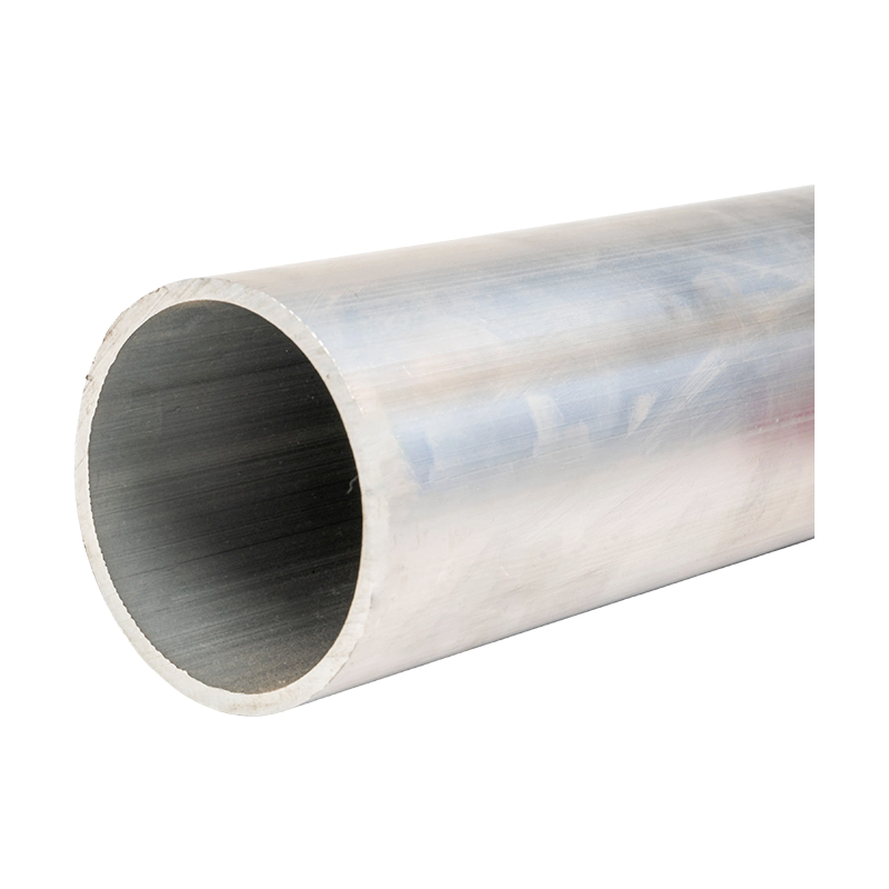
- Check tube straightness, ovality and surface condition. Reject tubes with deep dents or scoring where insulation will sit, and store them on timber rather than directly on the ground.
- Inspect post insulators and cast resin parts for chips, hairline cracks and contamination. A chipped shed usually shows up later as a failed hipot test.
- Confirm hardware grade, washers, bimetallic transition plates for copper-to-aluminum joints, and a calibrated torque wrench.
- Check the weather. Wind above roughly 10 m/s makes long tube lifts hard to control, and rain contaminates open joints.
If the conductor size is still open, settle it before mobilizing. Our guide on choosing the right aluminum alloy tubular bus bar covers current rating, diameter and support spacing trade-offs.
Step-by-Step Installation Sequence
The sequence below keeps rework low because it aligns supports before tubes arrive and leaves adjustment for last:
- Survey and mark support positions from the drawings, then measure the real span. If the as-built span differs from design by more than about ten percent, stop and have the spacing re-checked.
- Install base plates and structural steel, level and shim them, then grout or bolt to final tightness.
- Erect post insulators or support clamps and align them along one line. Verticality within roughly 2 mm per metre and consistent height keep the tubes from being forced into place.
- Pre-assemble tube sections, clamps and expansion joints on the ground wherever access allows. Ground work is faster, cleaner and safer.
- Lift and seat the tubes into the clamps, leaving sliding supports free to slide. A tube clamped hard at both ends of a long run has nowhere to move when it heats.
- Prepare each joint: wire-brush the aluminum contact faces, apply contact compound, assemble within the compound's working time, then fit the hardware.
- Torque in stages and in a diagonal pattern, then apply torque-marking paint so the check can be repeated visually after the first thermal cycle.
- Measure phase-to-phase and phase-to-earth clearances, and check straightness across the full run before recording torque values, ambient temperature and tube lengths.
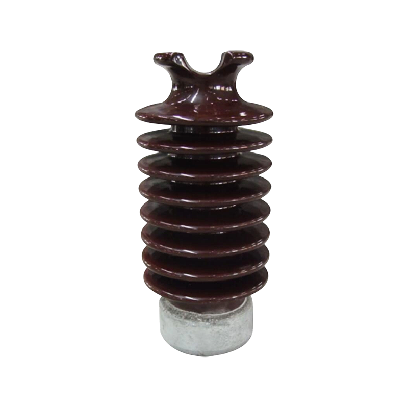
The insulator is the pivot of the whole sequence: it carries the tube weight, the short-circuit cantilever load and any expansion movement you failed to allow for. Select a post insulator rated for the actual cantilever duty of the bay rather than for the nominal voltage alone.
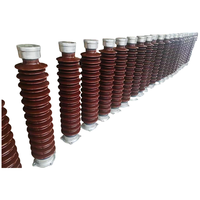 Post Insulators for Tubular Bus Bar SupportRigid insulating support for live conductors and bus bars in substations, switchgear, and tubular bus systems, rated for cantilever, seismic, and polluted conditions.View Product →
Support Spacing, Span and Alignment Tolerances
Support spacing is governed by four loads: the tube's own weight, short-circuit forces, wind or ice on outdoor runs, and seismic requirements. Thinner tubes and exposed outdoor bays generally need shorter spans, and the short-circuit study often reduces spacing further than intuition suggests.
| Tube outside diameter | Indoor span | Outdoor span | Typical application |
|---|---|---|---|
| 50-65 mm | 2.5-3.5 m | 2.0-3.0 m | Short links and low-current feeders |
| 80-100 mm | 3.5-5.0 m | 3.0-4.0 m | Wind farm collector circuits, 10-35 kV bays |
| 100-150 mm | 4.5-6.0 m | 3.5-5.0 m | Substation main bus with high short-circuit duty |
For alignment, expect straightness of about 2 mm per metre and no more than 10 mm cumulative over a run, with supports on a common line within 3 mm. Fix the tube at one end and let the other end slide. Aluminum expands at roughly 23 x 10^-6 per degree Celsius, so a 20 m run moves about 18 mm across a 40 degree swing. Bolt both ends hard and that movement goes into the supports and the insulator porcelain instead.
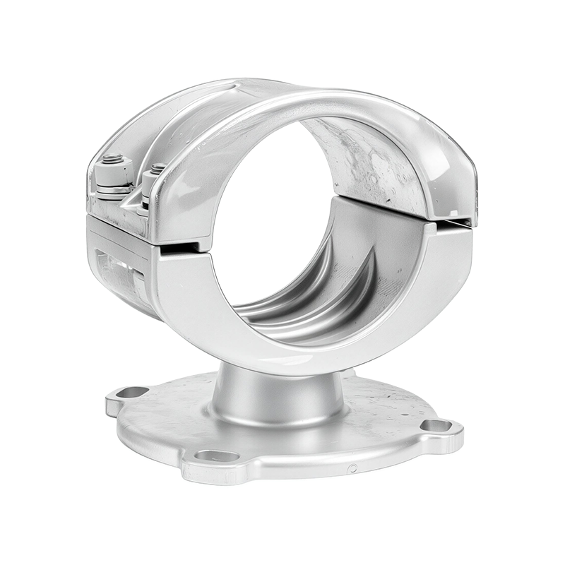
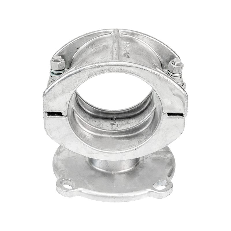 Fixed Bus Bar Supports and Tubular Bus Bar HardwareHot-dip galvanized fixed supports, end caps, and clamps secure tubular bus bars, accommodating alignment and thermal movement in switchgear and distribution systems.View Product →
How the Insulation System Changes the Installation
Fully insulated tubular bus bars are chosen for compact bays and polluted environments, but the installation differs by type.
Epoxy resin cast tubular bus bars
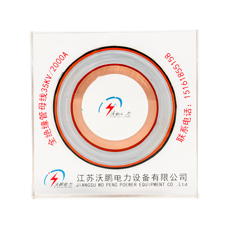
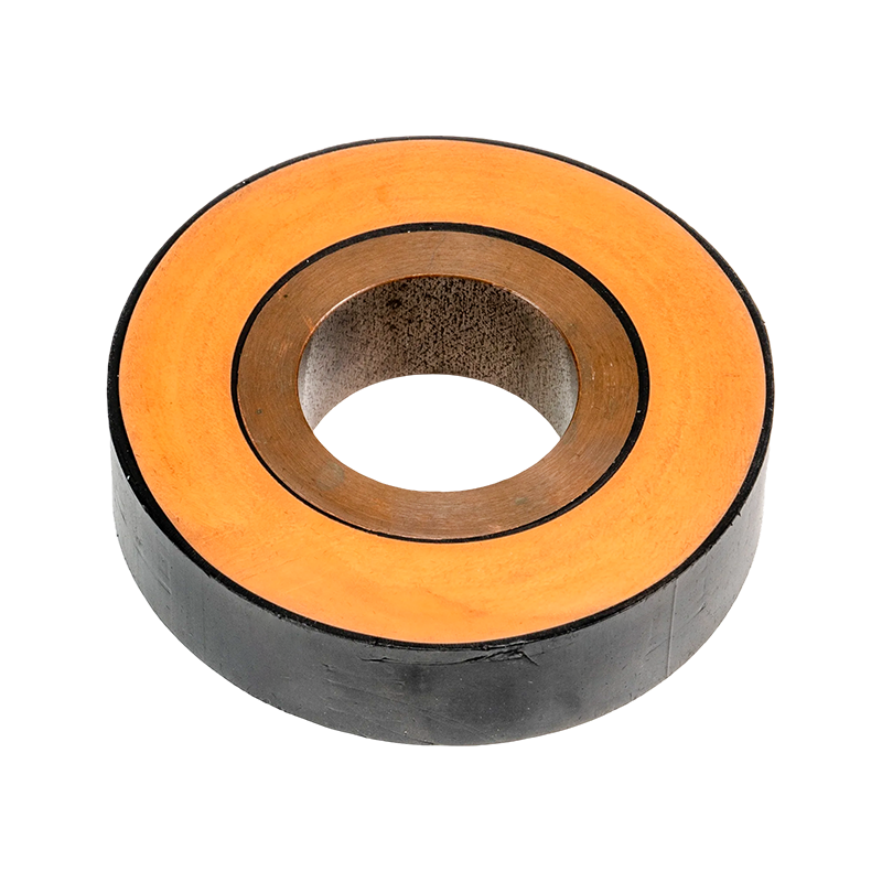
Factory-cast, rigid and relatively heavy. They cannot be flexed to close a misaligned gap, every extra kilogram loads the supports, and slings are mandatory — chain or hooks will chip the resin. Any chipped resin near a flange should be repaired or the section rejected.
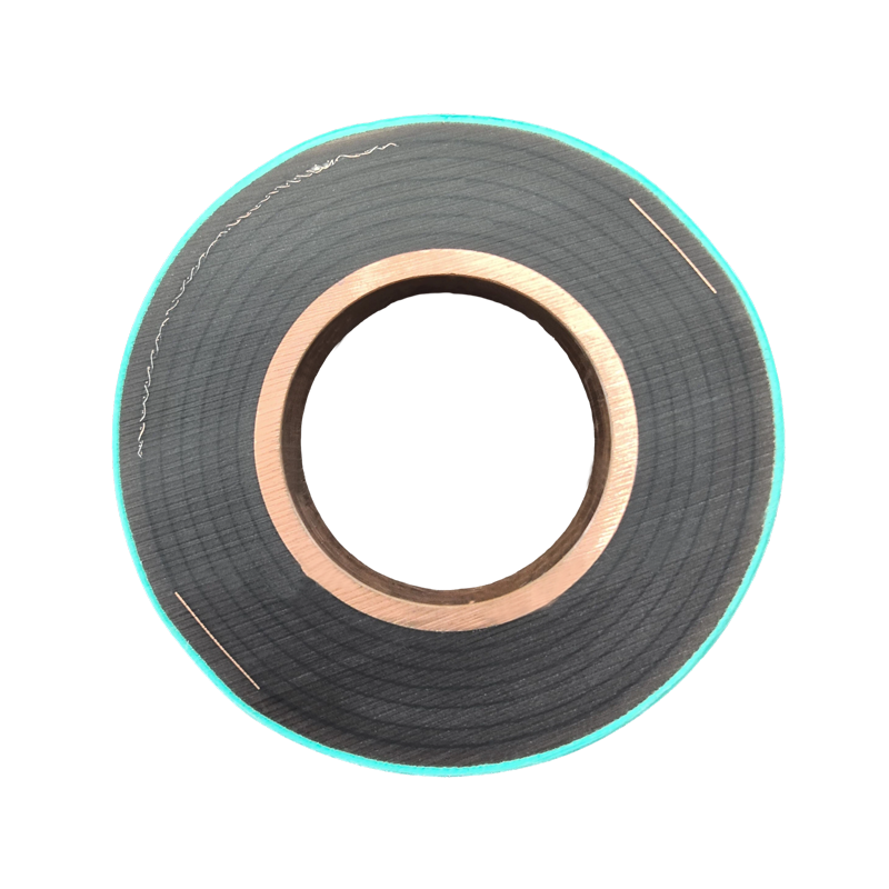 Epoxy Resin Cast Tubular Bus Bar SystemsFully insulated, vacuum-cast epoxy tubular bus bar with seamless joints, high copper content, flame resistance, and long service life for substation connections.View Product →
EPDM silicone rubber insulated tubular bus bars
Sleeved construction tolerates more misalignment, which helps on retrofit work. Keep joint areas and end seals sealed, and check that sheds are not pinched or trapped under the clamp.
PTFE insulated tubular bus bars
Low friction and good chemical resistance, but the surface scores easily. Leave the tube in its protective wrap until the moment it is lifted and avoid dragging the sleeve across burrs on the clamp or steelwork.
Whichever type you install, the insulated length must stay continuous through supports and joints. A bare metallic gap at a joint cancels the compact-clearance advantage and becomes the point where a fault starts.
Joint Preparation and Torque: Where Contact Resistance Is Decided
Aluminum forms an oxide layer within seconds, and that layer is an insulator. Every step of joint preparation exists to defeat it before the hardware goes on.
- Clean the contact faces with a stainless wire brush, then apply contact compound immediately.
- Assemble within minutes, not hours, and never leave a cleaned face exposed overnight.
- Use an overlap of at least one tube diameter unless the specification says otherwise.
- Typical torque for grade 8.8 steel hardware: M8 about 15-20 N·m, M10 about 30-40 N·m, M12 about 45-60 N·m, M16 about 90-120 N·m. The clamp manufacturer's figure always wins, and a calibrated torque wrench is not optional.
- Never bolt copper directly to aluminum; use a bimetallic transition plate.
Over-torque crushes thin-wall aluminum tubes, cracks cast resin bosses and strips threads. Under-torque is worse over time: the joint heats, the metal relaxes, contact resistance climbs and the joint heats further. Re-check torque after the first thermal cycle, typically 24 to 72 hours after energization, and record the numbers.
Inspection, Testing and Sign-Off
Commissioning is a short list, and every item leaves a record:
- Insulation resistance per phase with a 2500 V tester, recorded against the test date and ambient conditions.
- Contact resistance at each joint. A joint reading roughly double its neighbours should be opened and rebuilt rather than accepted.
- Clearance verification against the drawing for the highest voltage class present, plus a check for filings, tools and other foreign objects.
- Thermal imaging once the circuit carries load; joints should not run noticeably hotter than the tube itself.
FAQ
Can a tubular bus bar be installed without welding?
Yes. Most low- and medium-voltage runs are bolted through clamps or cast terminals, which keeps the installation reversible and serviceable. Welded joints appear where the highest current density and the lowest contact resistance are required.
How much expansion allowance does an aluminum tube need?
Aluminum expands by roughly 23 mm per 100 m of run for every 10 degrees Celsius of temperature change, so a 20 m run across a 40 degree swing moves about 18 mm. That is why one end of a long run should slide.
Why does a joint run hot after energization?
Usually oxide left on the contact faces, insufficient or uneven torque, or a copper-to-aluminum interface without a transition plate. Open it, clean it, re-assemble with compound and re-measure contact resistance.
Most tubular bus bar problems are not mysterious. They come from supports that were never aligned, joints that were never cleaned, and runs that were never given room to move. Get those three right and the bay passes its tests the first time. If a project needs support clamps, insulators or insulated tube sections matched to a specific layout and short-circuit duty, talk to our engineers while the drawings are still open, not after the tube is in the air.



-
 +86-180 3625 3000
-
 admin@wpbusbar.com
-
 No. 8, Yanjin Road, Chengxi Industrial Park, Shanyang Town, Baoying County, Yangzhou City, Jiangsu Province, China
Copyright © Jiangsu Wopeng Power Technology Co., Ltd.
All Rights Reserved.
 Custom Insulated Bus Bar Manufacturer
Tubular Busbar System Factory